
S-HX331R Four-Axis Soldering Robot by Southern Machinery
Hand soldering leaks labour and yield on THT lines. See S-HX331R four-axis soldering robot specs, line integration and a worked labour ROI example.
Oct 7, 2026 · Updated Oct 7, 2026 · Southern Machinery
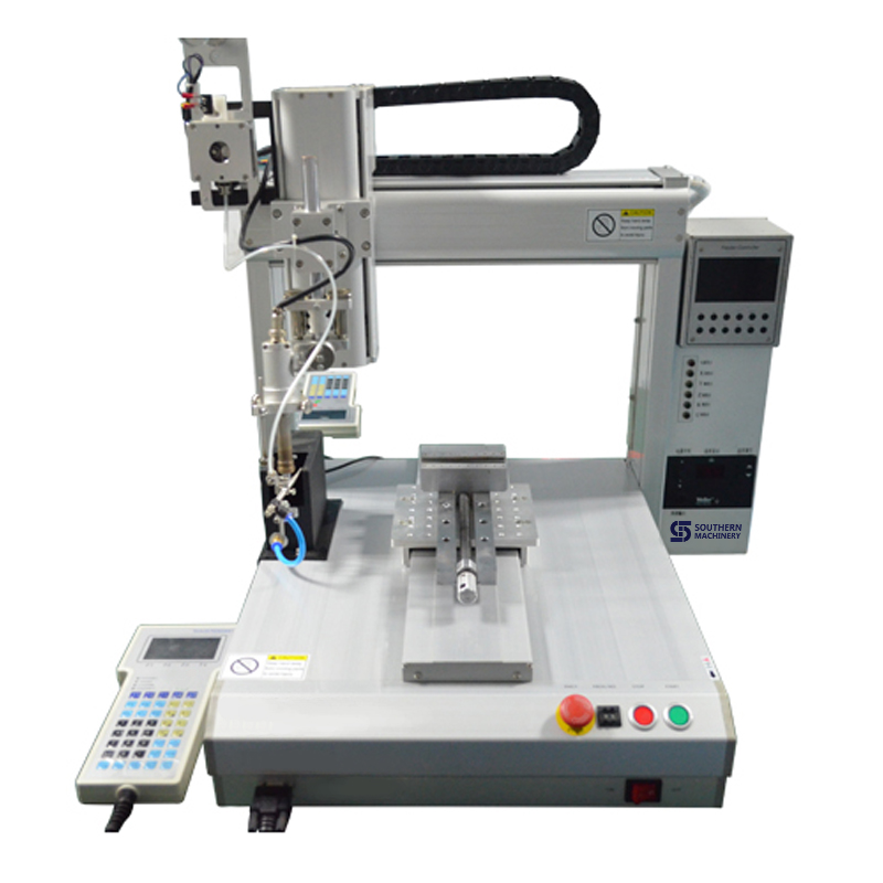
The S-HX331R is a four-axis rotary soldering robot that automates the soldering step on THT and mixed-technology PCB assembly. It travels on X and Y, adds a Z axis and a 360° R rotary axis, holds 0–500 °C at ±2 °C, and feeds solder wire by program instead of by hand. Its Southern Machinery datasheet states a verified value of one robot covering three workers, with a reject ratio class of 2 per mille (≤2‰).
What is a four-axis soldering robot used for?
A four-axis soldering robot replaces the hand-soldering bench inside a THT or mixed PCBA line. The S-HX331R handles spot soldering, drag soldering, and PCB wire, terminal and data-cable soldering — the joint types the factory sheet for the soldering platform lists as standard work. The fourth axis is the difference: X and Y move the head across the board, Z sets tip height, and R rotates the nozzle through 360°, so angled and side-entry joints run in the same program as flat ones.
Typical applications in an EMS or ODM factory:
- Angled and side-entry joints that force operators into awkward tip positions
- Dense, fine-pitch THT boards where dwell time decides between a cold joint and a bridge
- Connectors, terminals and wire-to-board joints that are hard to fixture by hand
- Mixed-technology and high-mix boards where the same joint pattern returns on a cycle, but a few joints would otherwise hold a whole panel back
Where does hand soldering leak labour and quality?
The S-HX331R datasheet frames the problem in five failure modes, and each one is a cost line rather than a technicality.
Angled joints defeat repeatable hand routines
Side-entry and rotated joints force operators into tip angles that are hard to repeat. A robot has no comfortable side — it reaches the joint at the same angle on every board.
Dense boards punish hesitation
On high-density boards the gap between a cold joint and a bridge is dwell time. Hands hesitate; the program does not, because temperature and path are stored per product rather than judged per joint.
Iron temperature drifts under load
An iron cools at every joint, and operators compensate by pressing harder. With control to ±2 °C across 0–500 °C, the machine holds the set temperature at the tip.
Solder feeding becomes guesswork without a program
Too much wire balls the joint, too little starves it, and hand feeding cannot hit the same fillet twice. The robot feeds tin by program, and a broken-tin function cracks the oxidized outer layer so fresh solder core reaches the nozzle with less wire wasted.
Headcount compounds with volume
Three workers per soldering task is the manual baseline quoted in the source document, and headcount and wages climb with volume. That is the line the robot attacks: 1 S-HX331R ≥ 3 workers is the verified value proposition, at a reject ratio class of ≤ 2‰.
Which S-HX331R specifications should you check first?
These values come from the official Southern Machinery S-HX331R datasheet, support initial evaluation, and remain subject to final technical confirmation against your board size, joint count and line layout.
- Model — S-HX331R four-axis rotary automatic tin soldering
- Temperature range — 0–500 °C, temperature error ±2 °C
- Solder range (X / Y / Z / R) — 300 / 300 / 100 mm / 360°
- Maximum load — 15 kg
- Movement speed — 0–800 mm/s
- Control resolution — 0.01 mm/s (per datasheet)
- Repeat accuracy — ±0.02 mm
- Program capacity — more than 100 sets
- Interpolation — 3-axis
- Input power — full-voltage AC110 V – 220 V
- External control interface — RS232
- Machine dimensions — 530 × 580 × 650 mm
- Weight — 69 kg
- Solder functions — feed tin and broken tin (solder breaker); soldering nozzle with heating core
- Extras — DVR video, remote control, HDMI, temperature-controlled switch, multi-function control switch
- Verified value — 1 S-HX331R ≥ 3 workers; reject ratio ≤ 2‰
Anything not on this list is not specified in the source document — contact Southern Machinery to confirm it for your application.
How does the robot fit into a complete PCB assembly line?
The robot is a station, not a line, and it inherits whatever the upstream process did to the board.
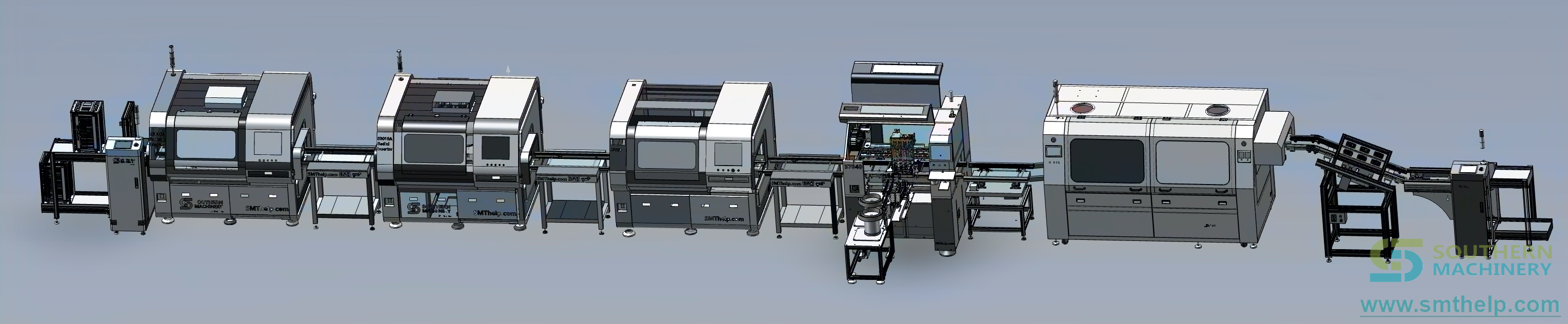
Upstream: THT auto-insertion
Radial, axial, odd-form and terminal insertion machines place and clinch the through-hole parts before soldering. The wider THT range is catalogued at smta.smthelp.eu/products/tht-auto-insertion, including the S7900 odd-form insertion machine.
In-station and after: wave or selective soldering
Mass joints go to wave or selective soldering; the robot takes the joints a wave cannot reach or should not touch. See selective soldering and wave soldering.
Fixtures, programming and the teaching box
PCB fixtures are designed from your samples — panel size, support points and clearance for the tip. Programs are taught on the handheld box with capacity for more than 100 sets, so a product change is a program call rather than a rebuild. RS232 connects the cell to PLC and MES data flow, and DVR video plus HDMI output give supervisors and auditors a live view. The single-robot comparison sits alongside the desktop solder robot family guide.
What does the labour maths look like on your own numbers?
Buyers rarely approve a robot on motion specs. They approve it on headcount, rework and throughput, so the arithmetic should be written down before the quotation.
Annual labour avoided = operators replaced x loaded hourly cost x hours x shifts x working days
Annual quality value   = (rework + scrap + test escapes) x your measured defect rate
Annual cost to run     = solder wire + tips + fixtures + power + maintenance
Net annual value       = labour avoided + quality value - cost to run
Example, not a quotation. Take the datasheet value of one robot covering three workers. Three operators × 8 hours × 250 working days is 6,000 operator-hours a year that move from hands to the machine. Multiply that by your own fully loaded hourly rate, add the rework removed by replacing a variable manual fillet with a programmed one, then subtract wire, tip, fixture and power consumption. Every number here is illustrative — the result depends on configuration, joint count and your labour market, and is subject to final technical confirmation. Southern Machinery prepares a board-specific ROI estimate, typically within 24 hours of your inquiry.
What quality and capacity value should you expect?
Three published figures do most of the work. Movement speed of 0–800 mm/s keeps the station from becoming the bottleneck on a volume part. Repeat accuracy of ±0.02 mm with 0.01 mm/s control resolution makes the same fillet repeatable across a shift, not just across a board. And the ≤ 2‰ reject ratio class puts the quality argument in the datasheet — measure your manual baseline first so the comparison is honest. The second-order benefit is traceability: a stored program, a DVR record and an RS232 data path let the soldering step be logged the way a reflow profile is.
Which options should be decided before ordering?
- Z + R rotary axes are standard, giving a 360° soldering range in one program.
- Feed tin and broken tin are built in, cracking oxidized wire so the fresh core reaches the joint.
- Custom tooling — nozzle and tip geometry designed from your pads, heating core matched to tip size.
- Process observation — DVR video, HDMI output and remote control for live observation and audits.
- Integration — RS232 external control interface for PLC and MES data flow.
- Production inputs — PCB fixtures designed from samples, plus wire diameter and alloy recommended per joint type.
How is the robot installed, programmed and supported?
Five steps: place the robot on a stable workbench and fit the custom PCB fixture; connect 220 V mains power (full-voltage AC110–220 V) — no compressed air for standard operation; set temperature, teach the paths and store the program; run sample boards and tune temperature, feed speed and tip height until every joint passes your acceptance criteria; then train and ramp. Installation and operator training are included free, with 24/7 support and a 1-day spare-part lead time after handover. At 69 kg it occupies bench space rather than floor space.
FAQ
What makes the S-HX331R a four-axis robot?
It combines the Z axis (vertical) with an R rotary axis, giving a 360° soldering range on top of the X and Y travels. Angled and side-entry joints are soldered in the same program instead of being re-fixtured.
What is the "broken tin" function?
The solder breaker cracks the oxidized outer layer of the wire before feeding, so the fresh solder core reaches the nozzle. With program-controlled feed timing it produces consistent fillets with less wire waste.
How fast and how accurate is it?
Movement speed from 0 to 800 mm/s with ±0.02 mm repeat accuracy and 0.01 mm/s control resolution, across 0–500 °C at ±2 °C. Fast enough for volume, precise enough for dense fine-pitch THT boards.
Can it connect to our systems?
Yes — the RS232 external control interface connects the robot to PLCs and MES data flow, and DVR video plus HDMI output support live observation and audits.
What utilities does it need?
Full-voltage AC110–220 V mains power; no compressed air for standard operation. The robot weighs 69 kg and sits on a stable workbench with your PCB fixture.
How many programs can it hold?
More than 100 program sets, so repeating products are recalled rather than re-taught.
Next step: send your board samples for a rotary soldering demo
Tell us which joints you hand-solder today — especially the angled, dense or terminal ones — with your board samples or drawings, the joint count per board and your monthly volume. You will get a configuration, quotation and ROI estimate, typically within 24 hours. Email info@smthelp.com or message WhatsApp +86 136 0256 2576. The wider machine range is browsable at file.autoinsertion.com, and machine photos at ph.smthelp.com.
Comments