
Universal 8223 (J11) Controller Troubleshooting Guide | Auto Insertion
Field-service guide to Universal 8223 (J11) controller faults: voltage windows, CPU LEDs, memory and serial I/O checks, plus repair or retrofit advice.
Sep 24, 2026 · Updated Sep 24, 2026 · Southern Machinery
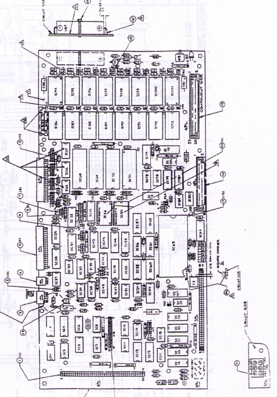
Universal 8223 (J11) Controller Troubleshooting | Southern Machinery
Legacy Universal Instruments auto insertion machines are still running production in thousands of THT and mixed-technology PCB assembly lines. Many of them are driven by the 8223 controller built around the DEC J11 CPU board — a platform that has been out of production for decades, yet still places radial, axial and odd-form components every shift.
This guide condenses the field-service information Southern Machinery publishes for its AI (auto insertion) spare parts and repair service customers into a single diagnostic reference: what to check first, what voltages are acceptable, how to read the CPU indicators, and when to repair, replace or retrofit.
It is written for maintenance engineers, equipment technicians and production managers who keep legacy THT lines alive — not for the lab.
What is the Universal 8223 (J11) controller used for?
The 8223 is the machine controller used on older Universal Instruments auto insertion platforms. It is a DEC J11-based CPU assembly that talks to the machine through an EMI/PS board, a local I/O box and optional external I/O boxes, and it runs the insertion programs that drive the head, the feeders and the X-Y table.
The practical consequence for a factory is that most "the machine is dead" symptoms on these platforms are not mechanical — they are controller power, connectors, socketed ICs or memory backup circuits. The controller is also unusually sensitive to one thing in particular: the +5 V supply. It tolerates wide variation on ±15 V DC and 24 VAC, but not on +5 V DC.
The diagnostic method documented in the source guide is deliberately sequential: check controller power first, then CPU indicators, then serial I/O, then local I/O, then external I/O. Skipping straight to the I/O cards is the most common cause of a "repaired" machine that fails again a week later.
Quick check list — the twelve things to verify first
These are the faults observed repeatedly in the field and are the correct first pass on any 8223 fault:
| # | Check | Why it matters |
| --- | --- | --- |
| 1 | +5 V set between 4.95 and 5.00 V, measured on J11 across C79 on the CPU board | The test points on the EMI/PS board do not accurately reflect the supply voltage |
| 2 | Intermittent power connections at the rear of the DC supply chassis — in particular the 3PL "RED BRICK" connector feeding +5 V, +15 V and −15 V to the J11 and I/O box | Poor contacts at 3PL give the J11 a low +5 V. Most common on older machines |
| 3 | Poor connections on the power cable at the back of the I/O box | Causes low voltage at the I/O box and J11. If a small PCB marked 433993xx MIB PWR ASSY is fitted, these connector issues are no longer a problem |
| 4 | Bent IC leads on socketed devices — IC19 on the memory expansion board is the usual suspect | Intermittent faults that survive a board swap if the socket is not inspected |
| 5 | Open fuses in the memory battery circuit — 1FU on the memory expansion board, 2FU on the J11 CPU board | Losing the battery circuit loses pattern data. J11 CPU 433797xx and J11 EXP MEM 43423001 have no fuse |
| 6 | Battery solder joint on the memory expansion board — resistance from the negative battery lead to ground should read a short (< 0.1 Ω) | A resistive joint looks fine until power is removed |
| 7 | EMI/PS board revision — the machine should carry 41693302 PC CD, EMI/PS ASSY, not 41693301 or earlier | A board change was issued to correct power-down behaviour |
| 8 | Cable between EMI/PS and the J11 CPU (10-wire shielded flat cable) when the system only powers up correctly every other time | Classic symptom of a failing shielded ribbon |
| 9 | Exec revision — 417247xx REV B and 405912xx / 405913xx REV L have a known power-down problem | Fixed by a power-fail modified J11 or a newer exec |
| 10 | Serial communications ICs IC65, IC66, IC67 — the receiver IC67 (MC3486 / 26LS32A equivalent) is easily damaged by ESD | IC65 = MC1488, IC66 = MC3487 / 26LS31C equivalent. Socketed versions are easy to replace |
| 11 | Jumper configuration against the machine documentation | A jumper moved during a previous repair is a silent fault |
| 12 | If the unit drops into ODT and will not accept console input, suspect IC43 and/or IC52 | See the known-failure section below |
Symptom-to-check map
| Observed symptom | First diagnostic path |
| --- | --- |
| No communications with console | Controller power → J11 CPU indicator state → console serial I/O |
| Improper communications with console | Controller power → IC43 and IC52 → console serial I/O |
| Fails to communicate with host or other serial I/O | Controller power → J11 CPU indicators → serial I/O ports |
| Trap errors | Controller power → memory voltage supply circuit → EMI/PS power timing → socketed ICs → memory test with the PFAIL program |
| Fails to power up in the EXEC program | Same path as trap errors, plus IC43 and IC52 |
| Loses pattern data | Same path as trap errors (memory backup circuit and battery) |
| Incorrect control of machine I/O — chattering valves, wrong DAC outputs, wrong encoder values | Controller power → local I/O → external I/O |
| Repeats outputting the UIC restart message | Controller power — the PINT indicator on the EMI/PS will be active |
Controller power: what to measure, and the acceptance window
Measure at the point indicated. Any variation needs to be investigated and corrected before moving on.
| Supply | Where to measure | Acceptable value |
| --- | --- | --- |
| +5 V | Do not use the 5 V test point. Use the Black test point (+5 V TP) on the MIB PWR adaptor card, or C79 on the CPU board | +4.90 to +5.00 V DC |
| +5 V cross-check | I/O box backplane, pin 80 (+5 V) and pin 76 (ground) | Difference from C79 must be less than 0.1 V; if not, inspect the Y adaptor cable |
| +15 V | Brown test point on the MIB PWR adaptor card or EMI/PS board | +14.6 to +15.00 V DC |
| −15 V | Red test point on the MIB PWR adaptor card or EMI/PS board | 14.6 to 15.00 V DC |
| 24 VAC | TP4 (Orange) on the EMI/PS | 20.0 to 28.0 V AC |
Three details from the guide that save hours:
- The J11 handles variation on ±15 V DC and 24 V AC, but not on +5 V DC.
- The 24 V AC path runs through the shielded ribbon cable between the EMI/PS and the J11 CPU board, then through a fuse on the J11 CPU board and out of 9PL. If there is no 24 V AC, check that whole path — not just the supply.
- The 5 V supply itself is typically set at 5.5 to 5.6 V at the supply chassis. The drop through the cables and connectors brings it down to the controller. If the supply reads correctly but the controller test point does not, the cable is the suspect — wiggle the connectors at the supply chassis, the I/O box and the Y adaptor cable behind the I/O box.
Setting the +5 V correctly
The J11 CPU board will operate with anything from 4.80 to 5.2 V, and the EMI/PS card carries a voltage detector that trips below 4.7 V and above 5.3 V (approx.). When it trips, it sends the J11 through a quick power-down timing sequence — which is what corrupts memory data on controllers without the power-fail modifications.
That is why the guide recommends setting the voltage as close to 5.00 V as possible: it leaves the maximum drift window on both sides. A controller set at 4.90 V only needs a 0.2 V drift to reach the 4.70 V trip point; the same drift from 5.00 V stays inside tolerance.
The DCOK indicator on the EMI/PS should be lit when the supplies are set properly. If the supplies are correct and DCOK is out, replace the EMI/PS board.
The PINT indicator
PINT (Power INTerrupt) on the EMI/PS indicates the power detector has seen an AC line interruption or an out-of-tolerance +5 V condition. After a power-up (with power off for roughly 15 seconds), it should be off and stay off. It can be reset by either removing power for more than 15 seconds, or by pressing the small pushbutton on the EMI/PS board. A PINT that keeps re-triggering points at the +5 V path or the EMI/PS itself.
CPU indicator LEDs: what they mean
Four CPU indicators, interpreted only once system power is confirmed good:
| Indicator state | Meaning |
| --- | --- |
| All on | The CPU is generally being held in reset — check system power, then the EMI/PS board, then the cable, then the J11 CPU board |
| LT1 on, others off | Normal operation — the system is running a program (true only when LT2–LT4 are off) |
| All off | The unit is in ODT mode — also normal |
| Any other combination | The CPU has generally detected a hardware problem; the J11 CPU assembly should be considered bad |
With all indicators on, the guide's isolation sequence is:
- Check supply voltages.
- On the EMI/PS, measure IC40 pin 3 — should be high (4.0 to 5.1 V) — and the anode of D5 — should read 10 to 15 V. If not, the EMI/PS is probably bad.
- On the J11 board, measure IC34 pin 5 (should be high, 4.0 to 5.1 V) and R18 on the side closest to 9PL (should be 10 to 15 V). If the EMI/PS was good and these are wrong, the cable is bad. If these are correct, the J11 CPU board is bad.
Memory backup, battery and socketed ICs
The memory voltage supply circuit keeps pattern data alive when the machine is powered down. It is verified in two states:
| Board | Test points | Powered | Unpowered |
| --- | --- | --- | --- |
| Memory expansion board | IC16 pin 28 and IC12 pin 28 | Greater than 4.8 V (otherwise the board is bad) | Greater than 3.0 V (otherwise check fuse 1FU and the battery) |
| J11 CPU board | IC101 pin 28 and IC97 pin 28 | Greater than 4.8 V (otherwise the board is bad) | Greater than 3.0 V (otherwise check fuse 2FU and the battery) |
Removing the memory expansion board to test the J11 CPU board will lose the data stored in the system. Back up patterns first.
Also inspect every socketed IC on both boards for leads that have bent under the package during installation. IC19 on the memory expansion board is installed in a socket on some versions even when it does not look like it.
To test the memory itself, load the PFAIL (DA01) program like an EXEC. It performs a memory sizing pass, then a memory test, then presents a > prompt. Enter M for the write/read test — if it reports an error the J11 is probably bad — or P to fill memory with data (enter 2 for the fill pattern, N for the power-fail memory loop and Y for the automated test). Use capital letters; some versions reject lower case.
Known failure points on the J11 CPU board
| Component | Device | Failure signature | Field test |
| --- | --- | --- | --- |
| IC43 | Signetics PLS159 | Generates the event clock (normally jumper-set for 1.0 ms). When it fails it drives the data bus continuously, so the microprocessor cannot read or write data properly | Remove the chip if socketed — if the controller then accepts console input, IC43 is the fault |
| IC52 | Signetics PLS159 | Generates board timing clocks including the 614.4 kHz clock required by the serial I/O chips; failure produces wrong frequencies | Pin 16 should show a square wave at 614.4 kHz and pin 12 should be low. A pulsing pin 12 means IC52 is bad |
| IC17 | SN74128 | Drives the DTOP and DTIP signals to the I/O box backplane. These sit next to the +15 V and −15 V pins, and a short between them damages IC17 — frequently causing the J11 to malfunction | Look for a discoloured or burned IC and check logic levels. Also confirm no jumper shunts are installed across the pins of connector 8PL |
| IC19 | — | Bent leads under a socketed IC on the memory expansion board | Visual and continuity inspection |
IC43 and IC52 fail most often on J11 CPU part numbers 4034830x, 4315450x, 4320900x and 4332990x.
Serial, console and I/O diagnostics
Console serial I/O (RS-232). Verify the jumper configuration of K20 and K13 against the system documentation — typically 9600 baud, RS-232. If an expansion serial I/O card is installed, remove it and place the RUN/HALT switch in HALT (ODT). Then:
- Scope IC67 pin 1 and press a key — a switching signal should appear. No signal points at the cabling between the J11 and the terminal.
- Scope IC65 pin 3 and press a key — in ODT the J11 echoes received data out of the transmitter, so a switching signal should be visible.
Serial I/O port test programs. Three ROM programs are labelled on the J11 cover: ASCII DUMP and DATA ECHO. Enter ODT, type the number given on the cover for the program, then G for GO.
- ASCII DUMP outputs the ASCII character set from the serial port. Deposit the port base address in the displayed register and press P to proceed.
- DATA ECHO receives data on one port and transmits it on another — deposit the two base addresses in R0 and R1. Typically one port is the console and the other is the port under test.
- For ASCII DUMP, start with the terminal connected to the console port; to test another port, move the terminal to that port or use a jumper cable to loop the port's output back to its input on the COMM INTC card.
The port base addresses documented for the COMM INTC assembly:
| Port | Base address |
| --- | --- |
| Console (J1, COMM INTC ASSY) | 17777560 |
| Host (J4, COMM INTC ASSY) | 17776500 |
| Channels 2–16 (J2/J3, COMM INTC ASSY) | 17776510 through 17776670 |
Local and external I/O. Local I/O sits in the I/O box the J11 is attached to. Two facts matter:
- A bad I/O card often makes other I/O cards — or the J11 itself — appear bad, and a replaced card can fix the symptom only for the same fault to return later.
- A problem in the local I/O box can produce symptoms that look like external I/O faults, because data to the external I/O boxes passes through the local box's data lines.
The effective method is a scope plus a short test program entered in ODT, with the clock disabled (all Kx jumpers in) while testing — and the clock jumpers returned afterwards. Write-loop and read-loop test programs at location 1000 are documented in the source guide (DSF0 = 166000, DSF1 = 166002, DSF2 = 166004, and so on). Observe DSF, DTOP/DTIP and the data lines while the loop runs, then remove I/O cards one at a time until the logic levels become correct. If they do not improve, either the J11 or the EMI/PS is bad.
Note also that the DTOP, DTIP and DSFx pins sit next to the ±15 V supply pins on the backplane. A short between them damages the J11, the EMI/PS and most other I/O cards — check that carefully.
ODT itself requires working knowledge of the Digital Equipment Online Debugging Technique. The command summary is short: n/ opens a location and shows its contents (octal), carriage return closes it, line feed closes and opens the next contiguous location, $n or Rn opens a processor register, G starts execution and P resumes execution.
Repair, replace or retrofit: a decision framework
For a controller this old, the diagnostic result should drive a commercial decision, not just a repair. A practical framework used on legacy THT lines:
- Power and connector faults — repair in place. Low cost, fast turnaround, and the most common root cause.
- Socketed IC and single-component faults (IC43, IC52, IC17, IC19, serial I/O ICs) — repair or board-level exchange. Confirm the CPU part number against the known-failing list before ordering.
- Memory backup and battery circuits — repair, then verify pattern retention through a full power cycle before returning the machine to production.
- Multiple simultaneous faults or a confirmed bad J11 CPU assembly — exchange the assembly. Carry a tested spare; the lead time on these parts is the real production risk.
- Machine structurally sound but controller unmaintainable — evaluate retrofit and upgrade instead of replacement. Legacy Universal/UIC platforms are routinely upgraded with automatic PCB loading/unloading, board handling, AC motor conversion and modern control interfaces, which extends machine life without a full capital purchase.
The deciding question is rarely the cost of one repair — it is the cost of unplanned downtime on a line that has no controller-level spare.
How the controller sits inside a complete PCB assembly line
The 8223/J11 controller is the machine-level brain of an auto insertion station inside a larger THT/SMT flow. Understanding where it sits clarifies what a controller fault actually costs:
- Upstream: bare-board and magazine loaders, destackers and board handling conveyors feed the inserter. Board handling is often already automated while the inserter itself is legacy.
- At the station: the auto insertion machine places axial, radial and odd-form through-hole components, cutting, bending and clinching leads. Feeder condition, insertion head jaw guide gap and centring all affect yield — and a controller fault stops all of it.
- Downstream: wave or selective soldering, then cleaning, inspection (AOI, X-ray counting, first article inspection) and depaneling.
- Across the line: SMEMA handshaking coordinates the stations. A controller that cannot hold its I/O state correctly breaks that handshake and stalls the whole line, not just one machine.
That is why most Southern Machinery service work on legacy inserters combines the controller-level repair with feeder, head and board-handling checks in the same visit.
ROI, quality and uptime perspective
- Downtime is the dominant cost. A controller fault stops the machine and, through the SMEMA chain, its neighbours. Diagnosis time — not repair cost — is usually the largest line item.
- A documented first-pass checklist shortens mean time to repair. Checking power and connectors before swapping I/O cards avoids the classic "repaired and failing again" cycle.
- Spare strategy changes the economics. Holding a tested controller assembly and the known-failure ICs turns a multi-day outage into a same-shift repair.
- Stable +5 V protects process data. Power-down corruption of pattern data costs a full re-teach of the insertion program — hours of engineering time that a correctly set supply prevents.
- Retrofit competes well against replacement on structurally sound machines: automatic board loading, handling and modern interfaces typically cost far less than a new insertion platform, while removing manual loading labour and its safety exposure.
Technical values quoted above are the published figures from the Southern Machinery 8223 (J11) controller troubleshooting reference (document part number 43380001, revision E). Machine configuration and the correct replacement part must be confirmed with Southern Machinery before ordering.
FAQ
What is a Universal 8223 (J11) controller?
It is the DEC J11-based machine controller used on older Universal Instruments auto insertion machines. It runs the insertion program and controls the head, feeders, X-Y table and I/O, communicating through an EMI/PS board and local/external I/O boxes.
Why does my 8223 controller keep losing pattern data?
Pattern data lives in memory backed by a battery circuit. Losses trace back to the memory voltage supply: check IC16/IC12 pin 28 on the memory expansion board and IC101/IC97 pin 28 on the J11 CPU board (above 4.8 V powered, above 3.0 V unpowered), then fuse 1FU or 2FU, the battery and its solder joint. A +5 V supply drifting toward the 4.7 V trip point also causes a quick power-down sequence that corrupts memory.
What voltage should the J11 +5 V supply be set to?
Set it as close to 5.00 V DC as possible — the accepted window is 4.90 to 5.00 V measured across C79 on the CPU board (not on the EMI/PS test points). The board itself runs from 4.80 to 5.2 V, and the EMI/PS detector trips below about 4.7 V.
Which parts fail most often on the J11 CPU board?
IC43 and IC52 (Signetics PLS159 timing/clock devices), IC17 (SN74128, damaged by shorts to the adjacent ±15 V backplane pins) and socketed ICs with bent leads — IC19 on the memory expansion board is the usual example. Serial receiver IC67 is easily damaged by ESD.
Can a legacy Universal auto insertion machine still be supported and upgraded?
Yes. Southern Machinery supplies AI spare parts, sub-assemblies, retrofit kits, repair kits, upgrading, training and overhaul services for legacy THT platforms, and can combine controller repair with board handling and automatic loading upgrades.
Does Southern Machinery repair controller boards, or only supply parts?
Both. Southern Machinery provides board-level and assembly-level repair covering controller, servo and sensor electronics — the same service line that covers JUKI CyberOptics laser sensor assemblies — alongside tested spare parts and exchange assemblies.
Contact Southern Machinery for configuration advice
Tell us the machine model, the controller part number on the board and the symptom, and Southern Machinery will confirm the correct replacement part or repair route.
- Jason Wu — jasonwu@smthelp.com | +86 13602562576
- Machine photos and product images: ph.smthelp.com
- Catalogues, drawings and documents: file.autoinsertion.com
- Company and product information: www.smthelp.com
Southern Machinery Sales and Service Co., Ltd — founded 2011, Shenzhen, China. SMT/THT PCB assembly automation equipment, spare parts and service for 237+ customers worldwide, with global support, spare parts supply and operator/maintenance training.
Comments