
Lead-Free Solder Pot Selection Guide: Titanium Mini Solder Pots (JF Series) by Southern Machinery
A lead-free solder pot is decided by four things: pot opening, pot depth, melting capacity and rated power — and by whether the pot body is titanium. This guide covers Southern Machinery's JF series titanium mini solder pots, eight published models from 500 W to 1800 W with a 30-600 °C range, a 45 mm deep pot and a tin slag collector. It explains what each published parameter tells you, the six checks to run before ordering, typical tinning applications, where the pot sits in a THT and Wave Soldering line, and exactly what the catalog does not publish.
Sep 20, 2026 · Updated Sep 20, 2026 · Southern Machinery
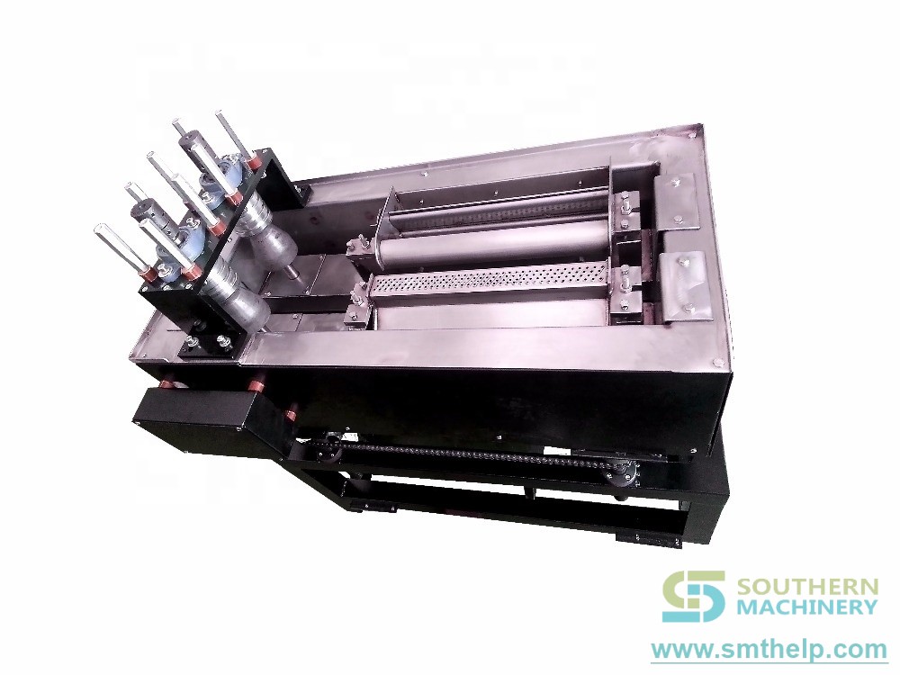
Lead-Free Solder Pot Selection Guide: Titanium Mini Solder Pots (JF Series) by Southern Machinery
A solder pot is the least glamorous machine in a PCB assembly plant. It is also the one that quietly decides whether your THT component leads, transformer windings and wire ends arrive at the insertion machine and the Wave Soldering machine already clean, evenly tinned and solderable — or whether your operators are re-touching joints two stations downstream.
This guide covers the JF series of titanium mini solder pots published in Southern Machinery's product catalog. It explains what each published parameter actually tells you, how to avoid the three specification mistakes we see most often, and what to confirm in writing before you buy. Every number below comes from the manufacturer's published parameter table. Where the catalog does not publish data, we say so instead of guessing.
In short: a lead-free solder pot should be selected on four things — pot opening size, pot depth, melting capacity and rated power — and the pot body should be titanium if you run lead-free alloys. The JF series publishes eight models from 500 W to 1800 W, all with a 30–600 °C range and a 45 mm deep titanium pot.
What is a solder pot used for?
A solder pot is a heated reservoir of molten solder used to tin or dip-solder metal parts by immersion. In electronics manufacturing it does three jobs:
1. Lead tinning before assembly. THT and odd-form components — transformers, relays, connectors, terminal pins, eyelets — are dipped so their leads are coated with fresh alloy before they reach a radial inserter, an odd-form inserter or a Wave Soldering machine.
2. Wire and cable tinning. Stripped stranded wire, magnet wire and harness ends are dipped to consolidate strands and produce a solderable end, which is faster and more repeatable than hand-soldering each strand.
3. Small-batch dip soldering and rework. Low-volume PCBA builds, sample runs and repair work are dipped where a full Wave Soldering setup is not economic.
A solder pot does not replace a Reflow Oven, a Pick and Place machine or a Wave Soldering machine. It prepares parts *before* those processes, which is exactly why its output quality is so easy to overlook — and why a badly specified pot creates defects that only surface several stations later.
Why "titanium" is the first specification to check
The pot body is the part of a solder pot that fails first. Molten lead-free alloys — SAC305, SnCu and similar — are significantly more aggressive to the iron and steel pots used with older tin-lead alloys. Over time the pot wall is eaten away from the inside, the alloy becomes contaminated with pot material, and the effective capacity drops. That is why pot material belongs at the top of your specification, not the bottom.
The JF series catalog states that the lead-free tin pot is made of titanium and is treated with a high-temperature anti-corrosion treatment, which is intended to give better temperature and corrosion resistance and a longer working life. We quote that as the manufacturer's published claim; the practical test is to confirm the pot material and treatment in writing for the specific model you order, and to ask how the supplier expects you to handle alloy changes.
The JF series at a glance: eight published models
All eight models share the same published temperature range of 30–600 °C, a titanium pot and a 45 mm pot depth. What changes is power, capacity and pot size:
JF-1070 — 500 W · melting capacity 2.3 · melting time approx. 15 min · machine 220 × 110 × 115 mm · pot 100 × 70 × 45 mm
JF-1611 — 1000 W · capacity 5.7 · approx. 20 min · 280 × 150 × 115 mm · pot 160 × 110 × 45 mm
JF-2010 — 1000 W · capacity 6.5 · approx. 20 min · 330 × 140 × 115 mm · pot 200 × 100 × 45 mm
JF-2580 — 1100 W · capacity 6.3 · approx. 20 min · 380 × 120 × 115 mm · pot 250 × 80 × 45 mm
JF-2510 — 1200 W · capacity 8.2 · approx. 20 min · 380 × 140 × 115 mm · pot 250 × 100 × 45 mm
JF-2516 — 1800 W · capacity 13.1 · approx. 20 min · 380 × 200 × 115 mm · pot 250 × 160 × 45 mm
JF-3080 — 1400 W · capacity 7.9 · approx. 20 min · 430 × 120 × 115 mm · pot 300 × 80 × 45 mm
JF-3010 — 1500 W · capacity 9.8 · approx. 20 min · 430 × 140 × 115 mm · pot 300 × 100 × 45 mm
One honest note on the published table: the melting-capacity column is printed without a unit. The values (2.3 to 13.1) most plausibly represent kilograms of alloy, but the catalog does not say so, so treat the unit as something to confirm with the supplier rather than something to assume. If you are sizing a pot on capacity, get that number in writing.
How to size a solder pot: six checks before you buy
1. The pot opening versus the footprint you actually dip
This is the single most common specifying error. The published pot sizes in the JF series run from 100 × 70 mm on the JF-1070 up to 300 × 100 mm on the JF-3010, with the JF-2516 offering the largest single opening at 250 × 160 mm.
Measure the largest *thing you will actually immerse* — not the size of the machine you bought it for. If you dip a whole 250 mm wide power supply PCBA in one pass, you need the JF-2516's 250 × 160 mm opening; if you only tin loose component leads in a basket or fixture, the JF-1070's 100 × 70 mm pot is enough. Buying on machine footprint rather than pot opening is how plants end up with a pot that cannot physically do the job it was bought for.
2. Pot depth and immersion depth
All eight JF pots are published as 45 mm deep. Depth sets how far you can immerse a part before the body, the insulation or the fixture hits the pot floor — and it is also what determines whether a dip can reach a full lead length plus board standoff. If your process needs deeper immersion than 45 mm, that is a question to raise before ordering rather than after.
3. Melting capacity and refill interval
Capacity decides how often someone has to top up the pot — and whether the pot keeps its thermal setpoint when a cold, large, thermally heavy part goes in. The published span is 2.3 to 13.1, roughly a five-fold difference across the range. A parts-prep station that dips continuously all shift wants headroom; a repair bench dipping two boards a day does not need to pay for it.
4. Rated power and heat-up time
The published power range is 500 W to 1800 W, and the published melting times are approximately 15 minutes for the 500 W JF-1070 and approximately 20 minutes for the rest of the range.
That second number matters more than it looks. A bench pot is usually switched on at the start of a shift and works all day; heat-up time is therefore a one-off daily cost. But if your process stops and restarts through the day — or if you run two shifts with a cold start — heat-up time becomes real lost minutes. Plan the warm-up into the shift routine rather than discovering it.
5. Temperature range and control quality
Every JF model publishes the same 30–600 °C settable range, which comfortably covers lead-free working temperatures and leaves headroom.
Control quality is where cheap pots and good pots diverge. The JF series catalog describes a microcomputer PID chip with one-button self-tuning and a saving function, phase-shift trigger control for a stable temperature, and a double digital display so the setpoint and the actual reading can be seen at the same time. Those details matter to your process because tinning quality is a function of temperature consistency: a pot that overshoots on recovery, or that sags when a heavy part goes in, produces uneven coating no matter how good your operators are.
The catalog also states the high-efficiency energy-saving infrared heating body can work in a 400 °C high-temperature environment for a long time, and that the multi-directional cooling holes provide quiet cooling. We report those as published specifications.
6. Service access and shop-floor practicalities
Three published details affect day-to-day usability rather than metallurgy:
- A tin slag collector — dross forms continuously on a lead-free pot and has to be removed without losing usable alloy. A dedicated collector is a maintenance feature, not an accessory.
- A separate power socket — the catalog notes this is so a damaged power cord is convenient to replace, and so a longer cord can be fitted if the work position requires it. That is a genuine consideration if your pot lives on a bench away from the nearest outlet.
- The control part is a microcomputer chip, positioned as the product's control interface.
Also plan the environment, because a solder pot is a hot, fuming machine: local fume extraction, a heat-resistant bench surface, clear clearance around the pot, and operator PPE are part of the installation, not optional extras. Flux fumes and dross handling are the two topics worth writing into your SOP before the machine lands.
Typical applications for a bench-top solder pot
The JF range is a bench-top machine — the largest model is 430 × 200 × 115 mm — and that shapes where it earns its keep:
- Transformer, inductor and coil lead tinning before the parts go to a radial insertion machine or an axial inserter.
- Wire, cable and harness end tinning, including stranded wire consolidation.
- Terminal, Faston and connector pin tinning ahead of terminal insertion.
- THT and odd-form component preparation on high-mix, low-volume lines where automated tinning is not justified.
- Small-batch and sample dip soldering, plus rework and repair benches.
- Power supply, LED driver, appliance control and instrument board production, where a handful of parts per board need tinning that the main line does not handle.
How a solder pot fits into a PCB assembly line
A solder pot is an off-line, stand-alone asset. It does not sit on the SMEMA conveyor chain, it has no board-transfer handshake, and it is not rated in CPH the way a Pick and Place machine or an auto-insertion machine is. Its throughput is governed by how many parts fit in one dip and how fast an operator can load and unload them — which is precisely why capacity, pot opening and heat recovery are the parameters that matter rather than a placement rate.
Placed correctly, it sits upstream of the assembly line:
1. Component and wire preparation at the pot.
2. THT / odd-form insertion — a radial inserter, an odd-form inserter, or a terminal inserter places the prepared parts.
3. Wave Soldering on the assembled board, where a properly tinned lead wets more predictably.
4. Inspection — SPI checks solder paste before reflow; AOI checks the assembled board afterwards. Neither inspects the pot. Tinning quality is verified by your own sample checks and pull tests, which is an argument for controlling pot temperature properly in the first place.
Two integration notes worth raising with any supplier:
- MES and traceability. If your plant records process data per asset, ask whether the pot's controller exposes any data or I/O interface. The published catalog does not describe one, so do not assume it can be polled — confirm it.
- Feeders and Nozzles. If your tinning step exists to feed an automated insertion cell, the pot's output standard has to match what the downstream Feeder and Nozzle tooling expects. Lead diameter, coating thickness and straightness all matter to insertion reliability, and it is worth aligning the pot specification with the insertion equipment specification in the same document rather than treating them as separate purchases.
ROI, quality and throughput: how to build the business case
We will not invent a payback figure for you. What we can do is tell you which variables actually drive the case, so you can model it with your own numbers:
Quality. Inconsistent tinning temperature is a direct cause of uneven coating, icicles and poor wetting downstream. A pot with PID control, phase-shift trigger control and a stable published temperature range attacks the defect at source rather than at rework. Every non-conforming joint you remove from the rework station is labour you stop paying for twice.
Throughput and capacity. In-house tinning removes the wait for an external tinning service and the transport handling that goes with it. Melting capacity, pot opening and recovery behaviour set how many parts you can process per shift — and the published melting time tells you what the morning costs before the first part is dipped.
Scrap and consumption. A titanium pot with a tin slag collector is about alloy economics as much as metallurgy: less pot corrosion means less alloy contamination, and controlled dross removal means you lose less usable solder. Both are the kind of recurring cost that a cheaper pot pushes onto the operations budget.
Risk. A bench-top pot is a small capital item attached to a hot, corrosive process. Selecting on material and control quality first — and confirming spare-part availability and technical support — is usually cheaper over five years than selecting on the lowest purchase price.
What Southern Machinery does not publish for the JF series
To keep this guide usable and honest, here is what is not in the published catalog and therefore not stated anywhere in this article:
- No list price, quotation, lead time or delivery schedule.
- No warranty terms or service-level commitment.
- No certification list (for example CE, UL or similar marks).
- No customer names or factory references for this product family.
- No published unit for the melting-capacity column.
- No published power consumption, air requirement or fume-extraction specification beyond rated power.
- No published data interface for MES integration.
- No cable, thermocouple or heating-element service life figures.
Any of these can be requested directly. They simply should not be assumed from a catalog page.
FAQ
Q: What is the difference between a solder pot and a Wave Soldering machine?
A: A solder pot is a reservoir of molten solder used to tin or dip parts by immersion — loose component leads, transformer windings, wire ends. A Wave Soldering machine pumps solder into a standing wave and solders an assembled PCB as it travels along a conveyor. A pot prepares parts off-line; a wave machine solders boards in-line. Many plants use both.
Q: Can the JF series run lead-free alloys?
A: The catalog describes it as a lead-free tin pot with a titanium body and a high-temperature anti-corrosion treatment, and every model publishes a 30–600 °C settable range. Confirm the specific alloy you intend to run, the pot material, and the alloy-change procedure with the supplier in writing before ordering.
Q: Which model should I choose for a 250 mm wide assembly?
A: On published pot sizes, the JF-2516 offers a 250 × 160 mm opening and the JF-2510 a 250 × 100 mm opening, so the choice depends on the second dimension as well as the footprint. Measure the largest item you will actually dip, and remember all JF pots are 45 mm deep — immersion depth is a separate constraint from opening size.
Q: How long does it take to melt the solder?
A: The catalog publishes approximately 15 minutes for the 500 W JF-1070 and approximately 20 minutes for the other seven models. Treat these as published approximations and plan a warm-up routine at the start of the shift.
Q: Is a solder pot a replacement for selective soldering?
A: No. Selective soldering is a programmable, in-line or cell-based process for soldering specific joints on an assembled board. A solder pot is a manual, bench-top tinning and dip tool for parts and small batches. They solve different problems and are usually specified separately.
Q: What should I confirm before placing an order?
A: Your maximum part or board footprint, your required immersion depth, the alloy you will run and its working temperature, the largest batch size between refills, whether you need fume extraction and a heat-resistant bench position, the unit of the published melting-capacity figures, and what spare parts and technical support the supplier can commit to. Southern Machinery will confirm each of these against the model you select.
Talk to Southern Machinery about your tinning process
Southern Machinery has designed and supplied SMT and THT PCB assembly automation equipment from Shenzhen, China since 2011 and has served 237+ customers worldwide, with full-line capability across SMT, THT, Wave Soldering, board handling, cleaning and inspection.
If you are specifying a lead-free solder pot — or reviewing the tinning step that feeds an existing insertion or Wave Soldering line — send us your part drawings, the largest footprint you need to dip, and your alloy and temperature requirements. We will tell you which JF series model fits, and be equally clear about what we need to confirm with you first.
- Catalog and technical files: browse the Southern Machinery document portal at file.autoinsertion.com — the mini lead-free solder pot catalog and the full product library are published there.
- Machine photos: see the product photo album at ph.smthelp.com.
- Talk to an engineer: Jason Wu — jasonwu@smthelp.com · +86 13602562576 · smthelp.com · LinkedIn: smtsupplier

Comments