
THT PCB Design Rules for Automated Insertion: A DFM Guide for Radial, Axial and Odd-Form Assembly
Machine insertion succeeds or fails at the design stage. A practical DFM checklist for THT boards: lead span, clinch clearance, fiducials and panel layout.
Sep 13, 2026 · Updated Sep 13, 2026 · Southern Machinery
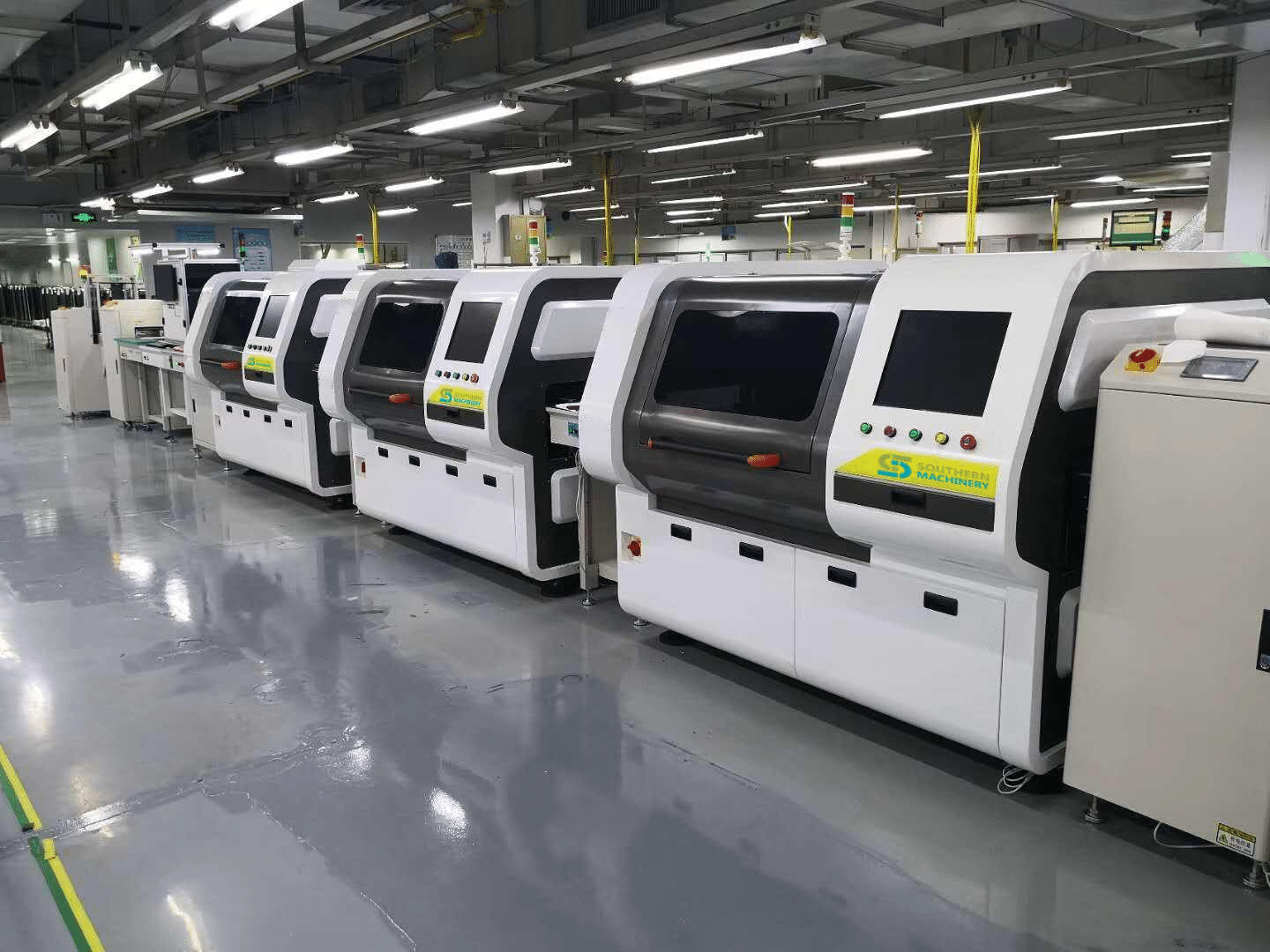
THT PCB Design Rules for Automated Insertion: A DFM Guide for Radial, Axial and Odd-Form Assembly
Through-hole boards are usually drawn by engineers who picture a row of operators with soldering irons and lead formers. Automated insertion changes the physics of that decision: the machine picks a component from a taped reel or tray, forms the leads to a set span, pushes them through your holes, and clinches them on the solder side in a fraction of a second. It can do that tens of thousands of times an hour — but only if the board is drawn to allow it.
Southern Machinery has built and serviced radial, axial and odd-form insertion systems in Shenzhen since 2011 and supports 237+ customers worldwide. This guide collects the design rules that decide whether automated THT insertion runs smoothly, using the published specifications of our inserters as the reference points.

What is this equipment used for?
THT auto-insertion machines place through-hole components into a PCB automatically: radial inserters handle tape-packed radial-lead parts (capacitors, transistors, LEDs, key switches), axial inserters handle taped axial parts and jumper wire, and odd-form machines handle the non-standard shapes — connectors, terminals, relays, transformers, eyelets — that no standard head can feed. After insertion the lead is clinched under the board, and the board goes to wave soldering, lead trimming and inspection like any other THT product.
The machine's capability is fixed at the factory; the board layout is what you still control. Every design decision below either stays inside the machine's envelope or pushes your component onto a manual bench.
Why design rules matter more for THT than for SMT
SMT placement is a surface operation: the nozzle puts a part on a pad and the reflow oven does the rest. THT insertion is a mechanical operation in three dimensions — the lead must reach the hole at the right angle, the body must be formed to the span your head supports, and the clinch must have space to bend the lead. Manual insertion operators unconsciously absorb that tolerance; a machine cannot.
That is also why automated insertion is worth designing for. Manual DIP lines are known for exactly the defects the S-70LD page lists as the typical condition of manual electronic machining: floating leads, leakage, misinsertion and reverse insertion, with output that depends on operator skill. Consistent machine insertion removes that variability — if the design lets it.
Design rules that matter most
1. Match your component lead spans to the insertion head
Insertion heads are configured for a fixed set of spans, and one head cannot cover everything:
- S-3000 radial inserter: dual span 2.5 / 5.0 mm
- S-3010 series radial inserter (off-line): four spans 2.5 / 5.0 / 7.5 / 10.0 mm
- S4000 axial inserter: component lead span 5–22 mm
Design implication: group components by span and order the head configuration to match the board family you build most. If one board mixes 2.5 mm and 10 mm radial spans, plan which head covers which run — or accept that the odd span goes in manually.
2. Leave a clear clinch zone on the solder side
After insertion the lead is bent over to hold the part. On the radial machines the clinch length is 1.5–2.2 mm at a clinch angle of 10–35 degrees. On the S4000 axial inserter the clinch lead angle is adjustable from 0 to 45 degrees, and the clinch lead length is adjustable from 1.28 mm to 1.80 mm, measured from the center of the insertion hole to the end of the lead.
Design implication: keep the solder side around every inserted hole free of SMD parts, vias, test points and signal traces — the clinched lead owns that area. This is also the reason wave-solder pallet openings and support pins must be planned together with the insertion layout.
3. Keep the panel inside the machine envelope
The S-3000 and S-3010 series radial inserters accept PCBs from 50 × 50 mm minimum up to 400 × 380 mm (S-3000) and 400 × 400 mm (S-3010B), with a board thickness range of 0.79–2.36 mm.
Design implication: size your panelization and breakaway rails for the machine you are buying, not for the largest board the product team can imagine. Transport edges also have to survive the conveyor, so keep components and tall parts off the clamping and conveyor contact zones.
4. Add fiducials and lock component orientation
Radial machines correct hole position with a machine-vision coordinate system, and the insertion direction can be set anywhere from 0 to 360 degrees in 1-degree increments. The S4000 axial inserter uses a vision system for positioning and insertion alignment and inserts at 0, 90, 180 or 270 degrees.
Design implication: put fiducials on the board and keep them clear of components and tooling; orient axial parts in 90-degree multiples so the head does not need a rotation the program cannot deliver; and keep body heights consistent so the insertion head has clearance to travel.
5. Specify a supply format the feeder can actually accept
A machine inserts what it can feed. Radial inserters are built for standard tape-packed radial-lead components — capacitors, transistors, LEDs and key switches. The axial S4000 handles taped axial components and jumper wire at the same time, and can insert jumper wire independently. Odd-form parts need trays, bulk feeders or custom grippers made for the part.
Design implication: check that every THT part on the BOM is available in a tape, tray or bulk format your feeder family supports. If it is not, either budget a custom feeder or leave it manual — and make that decision during design, not during line commissioning.
6. Design the board for the whole line, not just the inserter
Insertion is one station. The board still travels through board handling, wave soldering, post-wave lead cutting, inspection and cleaning. Southern Machinery links SMT, THT, AOI and wave soldering stations with consistent transport heights, so the same edge clearance rules apply along the whole line.
Typical application scenarios
- Power supplies and adapters — transformers, electrolytic capacitors and bridge rectifiers on THT-heavy boards
- Automotive electronics — car audio, vehicle power supplies and controller boards with mixed SMT/THT content
- LED lighting — driver boards, tube and bulb PCBs with radial capacitors, inductors and bridges
- Home appliances — air conditioner, TV, microwave, kettle and induction cooker control boards
- Industrial control and instruments — terminal blocks, relays and connectors that no SMT nozzle can place
- EMS and ODM production — high-mix lines that need the same board to run reliably across shifts
Key parameters to confirm before you order
- Component families and lead spans the head supports (radial dual/four span; axial 5–22 mm)
- Board size and thickness limits (for the S-3000/S-3010 series: 50 × 50 mm up to 400 × 380/400 mm, 0.79–2.36 mm)
- Clinch length and angle options, and the solder-side keep-out they require
- Feeder types for each component family (tape, tray, bulk, custom gripper)
- Vision/fiducial requirement and offline programming software for the line
- Utilities and environment: 220 V AC single phase 50/60 Hz, 0.6 MPa air at 0.3 m³/min, 10–35 °C ambient for the radial machines
- In-line vs off-line operation, and how the machine hands off to wave soldering
ROI, quality and throughput perspective
Machine insertion pays back on labour and consistency at the same time. The S4000 product page states the case plainly: one machine, with one operator, can complete the production capacity of forty people doing manual plug-in. The radial S-3010 series is rated at up to 22,000 CPH and the S-3000 at 18,000 CPH (the catalog also lists realistic running speeds of about 13,000 CPH and 10,000 CPH respectively) — output that stays flat across shifts instead of drifting with operator experience.
The quality side is where design discipline compounds. Vision-assisted coordinate correction, formed leads and controlled clinching remove the floating, misinserted and reversed components that manual lines generate, and fewer defects mean less touch-up, less rework and cleaner traceability data for your customers.
FAQ
What through-hole components can be inserted automatically?
Radial tape-packed parts (capacitors, transistors, LEDs, key switches), taped axial components and jumper wire, plus odd-form parts such as connectors, terminals, relays and transformers when they are presented in a tray, bulk feeder or custom gripper.
Can one machine handle both radial and axial components?
No. Radial and axial insertion use different heads, forming tooling and feed systems — they are separate machine families (for example the S-3000/S-3010 series radial inserters and the S4000 axial inserter). Many THT lines run both, plus an odd-form machine for non-standard parts.
How do I know if my PCB is designed for automated insertion?
Check four things: lead spans match an available head configuration, the solder side is clear around every clinched lead, board size and thickness sit inside the machine envelope, and fiducials plus consistent component orientation are in place for the vision system.
What board sizes and thicknesses can these inserters handle?
The S-3000 and S-3010 series radial machines accept boards from 50 × 50 mm up to 400 × 380 mm / 400 × 400 mm and thicknesses of 0.79–2.36 mm. Always confirm against the current spec sheet for the exact model and head configuration.
Does Southern Machinery supply feeders, spare parts and training?
Yes. Southern Machinery supplies the machines, custom feeders and grippers, spare parts, retrofit and upgrade kits, plus installation and operator training, with spare-part support for the installed base.
Can Southern Machinery review my board layout before I buy a machine?
Yes — send your Gerber data and BOM. We can check lead spans, clinch clearance, board handling and feeder feasibility against the machine you are considering, and publish design guidance resources such as the PCB Design Guideline and Through Hole Design Guidelines on smthelp.com.
Talk to Southern Machinery before you finalize the layout
Automated insertion is easiest to design in at the start and most expensive to retrofit later. Send Jason Wu your board files and component list and we will tell you which head configuration, feeder types and clinch options your product needs — and which parts should stay manual.
- Email: jasonwu@smthelp.com
- Website: www.smthelp.com
- Machine photos: ph.smthelp.com
- Catalogs and files: file.autoinsertion.com
Product specifications referenced above come from the Southern Machinery product pages for the S-3000 radial inserter, the S-3010B radial inserter, the S4000 axial inserter and the S-70LD odd-form inserter. Confirm final parameters during quotation.
Comments