
THT Odd-Form Insertion Case Study: 20 Types, Five Cells, 900 Boards/h by Southern Machinery
Power-supply PCB case: 20 odd-form types across five linked DD-8700 cells, 7-8 s panels, 900 boards/h and bottom-die clinching before wave solder.
Oct 6, 2026 · Updated Oct 6, 2026 · Southern Machinery
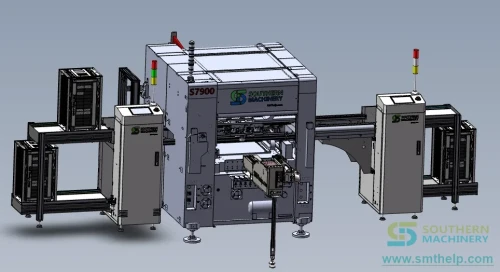
Direct answer: a THT odd-form insertion line automates the through-hole parts no SMT nozzle can place - tab terminals, multi-pin connectors, optocouplers, relays, switches and safety capacitors. The case behind this article is a power-supply (SMPS) board carrying twenty odd-form component types, moved off a hand-insertion bench onto five linked DD-8700 insertion cells: a 13.3 m line rated 0.4-0.8 s per component and 900 small boards per hour at its bottleneck. Every figure below is quoted from the customer solution deck for that line.
What is a THT odd-form insertion line used for?
A THT odd-form insertion line is used where a board carries through-hole parts that no pick-and-place feeder accepts. This board is a 94V-0 power-supply panel, panelled 1x2, carrying twenty odd-form types.
The problem the bench creates
Twenty hand operations per panel fix insertion headcount to the part list: when the mix grows, the bench grows with it, and every new operator relearns seating, polarity and clinch feel at their own speed. A hand-seated connector can stand proud by half a millimetre, pop out in the conveyor, or sit reversed - and the cost surfaces after the wave, as rework.
What the documented line replaced
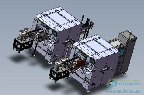
The deck assigns all twenty types to five insertion cells, one to four heads each. The evaluated line runs loader, two insertion cells, conveyors, a lift module, the retained manual segment for red-marked parts, then wave solder and unloader - 13,300 mm in total. The fully automatic option replaces that segment with three more cells for a 14,750 mm line.
Which odd-form components can the line actually insert?
The case part list: 187 and 250 tab terminals, yellow, white and blue VH connectors from two to seven pins, pin headers, optocouplers, eight-pin IC blocks, side-press switches, buzzers, safety and high-voltage capacitors, and a relay. Deformation-prone secondary-processed parts are marked red and stay hand-inserted by design.
Five feeding technologies, one platform
- Vibratory bowl - bulk parts. Orients loose connectors, headers and capacitors, screening direction and cosmetic defects.
- Tube rack - boxed parts. Polarity is fixed by the packaging itself; packaging cost is near zero and the tubes are recyclable.
- Taped feeder - multi-pitch carriers. Vertical feeders step taped parts at 2.5 / 3.5 / 5.0 / 7.5 / 10 / 15 mm pitches, checking polarity at every index.
- Tray magazine - trayed parts. Trayed ICs, amplifiers and heavy parts feed from stacked magazine trays.
- Reel and tandem - tab terminals. 187 and 250 terminals run on dedicated reel feeders with built-in cutting, sharing one feeder format.
How does five linked cells reach 900 boards per hour?
The deck does the arithmetic in public, including the bottleneck: each cell inserts at 0.4-0.8 s per component and passes a board forward in three seconds.
Documented cell balance (solution deck summary slide)
- Cell 1 - 4 types, 5 pieces per board, 2.5 s insert, 3 s pass: 8 s panel cycle, 900 small boards/h
- Cell 2 - 4 types, 5 pieces per board, 2.5 s insert, 3 s pass: 8 s panel cycle, 900 small boards/h
- Cell 3 - 4 types, 4 pieces per board, 2 s insert, 3 s pass: 7 s panel cycle, 1,000 small boards/h
- Cell 4 - 4 types, 5 pieces per board, 2.5 s insert, 3 s pass: 8 s panel cycle, 900 small boards/h
- Cell 5 - 4 types, 4 pieces per board, 2.6 s insert, 3 s pass: 7.8 s panel cycle, 923 small boards/h
Line throughput is set by the slowest station: 900 small boards per hour, or 450 panels. The deck's per-station tables list 0.5-0.7 s insertion speed while its summary uses 2-2.6 s per cell - a reminder to quote cycle times per part, not per brochure.
Why the clinch matters at line scale
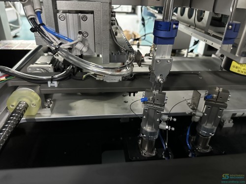
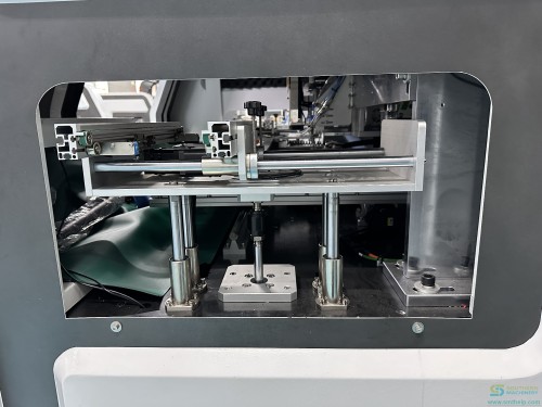
As each head presses, the bottom die rises in sync, a circuit test confirms the lead passed the hole, and only then does the die bend the legs. At line scale the clinch earns a second job: bent legs stop parts from earlier cells being pushed out downstream.
How does the insertion line connect to a full PCB assembly line?
The deck's line drawings include the full transfer set - loader, conveyors, lift module and unloader around the cells. Panels then leave insertion for wave solder, where clinched legs survive the tin wave; the deck states the clinch is what lets several cells run in series safely.
- Insertion platform: odd-form insertion machine
- Four-head companion platform: S7000 odd-form insertion machine
- Upstream axial insertion: S4000 axial auto-insertion machine
- Downstream soldering: wave soldering machine
- Full range: THT machine category
Which parameters decide your configuration?
Quoted from the DD-8700 technical parameter table in the solution deck.
Core machine parameters
- Model - DD-8700 fully automatic odd-form insertion machine
- Insertion speed - 0.4-0.8 s per component (depends on the part)
- Insertion heads - 1-4 per machine, each feeding a different odd-form part
- Insertion direction - 0-360 degrees, settable in 1-degree steps
- PCB load / unload - 3 s; board size - 100 x 100 mm to 380 x 280 mm, larger by custom
- Motion resolution - 0.001 mm per pulse; lead condition - bend within 0.1 mm
- PCB requirements - clampable edge at least 5 mm; hole at least 0.5 mm; bodies at least 2 mm apart (high-density option available)
- Programming and data - online vision programming, Excel-style process editor, USB import, RS-232C
- Motion and drive - Panasonic servos; THK ballscrews (0.01 mm class); AirTAC cylinders; SMC valves
- Control and display - self-developed industrial PC plus motion card on a 17-inch colour LCD
Companion platform
- DD-8700 - 0.4-0.8 s per piece, cam-driven heads, boards up to 380 x 280 mm
- DD-9000 - 1-2 s per piece, gantry with Y servo dual-drive and three 500 W cameras, boards up to 450 x 300 mm
What does the line replace on the hand-insertion bench?
Payback formula (simple model)
simple payback (months) = line price / (operators freed x loaded wage x hours per day x working days per month)
Worked example - illustration only, example values, not a quotation
- Operators removed from insertion: 10 (example); loaded wage: $4.00/h (example)
- Working hours per day: 20 (example); working days per month: 26 (example)
- Monthly bench labour addressed: 10 x $4.00 x 20 x 26 = $20,800
- Annual bench labour addressed: $249,600
- At a quoted line price of $300,000 (example): payback = 300,000 / 249,600 = about 14.4 months
These are example values, depending on configuration, and subject to final technical confirmation against your own quotation. The model ignores rework avoided after wave solder, the WIP a bench queues and the supervision one attendant replaces - all of which shorten the real figure. Use it as a floor, not a forecast.
What does the floor need before the crates open?
- Power - single-phase 220 VAC 50/60 Hz, 2 kVA per machine; five cells, five supplies
- Compressed air - 5-6 kg (0.5-0.6 MPa) at 0.6 m3/min per machine, dry and clean
- Environment - 10-30 degrees C, 30-70 % RH
- Footprint - 1950 x 1500 x 1530 mm main unit at 1500 kg; documented line 13.3-14.75 m long
- Board prerequisites - as in the parameter list above; leads straight within 0.1 mm
- Commissioning - teach the board with the vision program, import data by USB, run the part list cell by cell
FAQ
What counts as an odd-form component?
Anything an SMT nozzle will not handle: tab terminals, multi-pin connectors, boxed optocouplers and relays, trayed ICs, taped capacitors, switches and buzzers.
How fast is the insertion, and what does the line produce?
The deck rates 0.4-0.8 s per component with a 3 s board change; on this 1x2-panelled board it computes 7-8 s per panel, or 900-1,023 small boards per hour.
Why keep a manual segment at all?
The deck marks deformation-prone, secondary-processed parts red and leaves them hand-inserted. Automation that respects the part list beats automation that fights it.
How are the legs held before wave solder?
The bottom die rises with the press, confirms the lead passed the hole by circuit test, then bends the legs - so earlier parts cannot pop out downstream.
Can one machine mix all five feeding types?
Yes - heads mount bowl, tube, taped, tray or reel supplies, 1-4 heads per cell, each head its own part.
Send the board. We will send the station plan.
Tell us the parts your bench keeps inserting. Southern Machinery has built SMT and THT assembly and cleaning equipment in Shenzhen since 2011, serving 237+ customers worldwide with spare parts, retrofit, training and overhaul support.
- Request an insertion evaluation: info@smthelp.com or WhatsApp +86 136 0256 2576
- Documents behind this case: catalogue / solution / readiness checklist / operation manual
- Machine catalogue: file.autoinsertion.com
Comments