
STF1003 Tube Feeder Line Integration by Southern Machinery
Tube feeder line integration is the work that turns a stacked tube feeder into a working station: choosing a host machine it can mount to, deciding whether it talks to that host over IO or runs self-controlled, and provisioning 24 V DC, compressed air and a keyed feeder plate. The Southern Machinery STF1003 presents stick-mounted relays, terminals, transformers and capacitors from 3 x 3 x 3 mm to 25 x 25 x 25 mm to SMT mounters, odd-form machines and robot cells, and the product sheet lists installations on Panasonic CM602, JUKI, YAMAHA and Mirae platforms. This guide covers the three integration decisions, the documented compatibility, the parameter checklist, a handling-time calculation marked as an example, and the commissioning and shift checks that keep the station fed.
Oct 15, 2026 · Updated Oct 15, 2026 · Southern Machinery
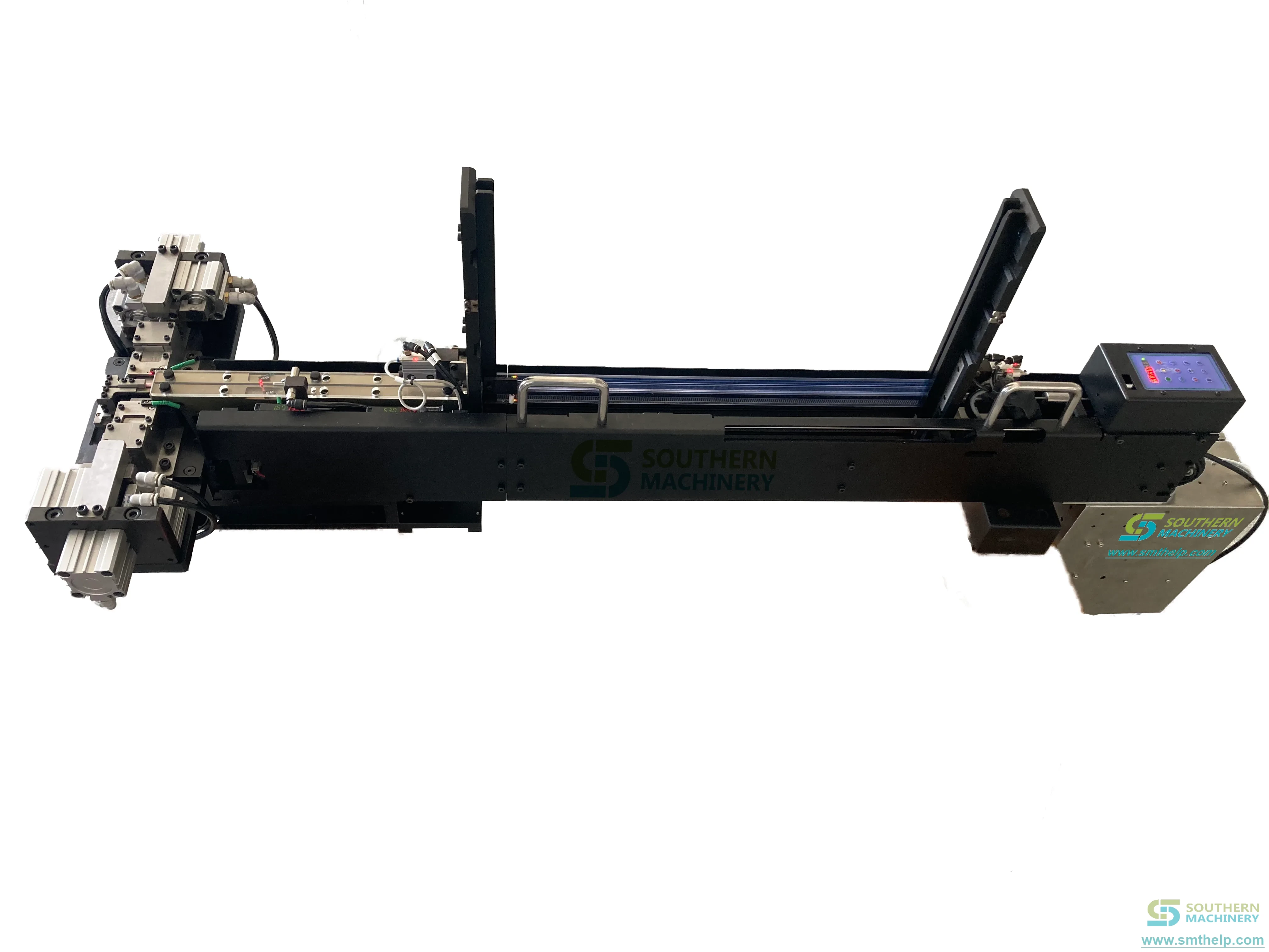
The STF1003 is a stacked tube feeder that presents tube-mounted relays, terminals, transformers and capacitors to an SMT mounter, an odd-form machine or a robot cell, one component at a time, from a magazine that holds the next tube. Tube feeder line integration is everything around that mechanism: choosing a host the feeder can mount to, deciding how it talks to that host, and provisioning the power and air it needs so the part arrives where the nozzle can take it.
What is the STF1003 tube feeder used for on a PCB assembly line?
Tube-mounted parts arrive in sticks because the stick protects long leads. Relays, heavy terminals, transformers, square capacitors and round capacitors are the families the STF1003 product sheet names, inside a component envelope from 3 x 3 x 3 mm to 25 x 25 x 25 mm.
Where tube-fed parts sit today
Odd-form and heavy through-hole parts usually land after SMT reflow and before wave soldering, and they are the parts that resist tape and reel: long-lead transformers, screw terminals, big relays. On most lines they are the residue of the BOM that no tape feeder can carry, handled at a station by one operator with a stick in each hand. The STF1003 replaces that packaging removal and presentation, not the insertion itself - the head still picks and places, and the nozzle, insertion program and board support are unchanged.
What does tube feeder line integration involve on a real line?
Integration is three separate decisions that fail independently. The product sheet frames them as mounting, communication, and holding the part long enough for the nozzle to take it - each with a documented answer rather than an assumption.
Mount, communicate, present
Mount means occupying a feeder slot: the footprint is 1350 x 92 x 115 mm at 25 kg, so it keys into a feeder plate rather than standing on the floor. Communicate means telling the host when a component is in position. Present means the part survives the track without losing its orientation or bending its leads. Beyond those three, the feeder asks the line for only a 24 V DC supply and clean compressed air, which is what makes it a station-level retrofit rather than a line redesign.
Which host machines will accept an STF1003?
The product sheet lists installations on Panasonic CM602, JUKI, YAMAHA and Mirae odd-form machines, and in each case states the feeder works alongside bowl feeders and radial tape feeders on the same platform. It also states the feeder automates tube-mounted components - DIPs and transistors among them - for SMT machines, for non-standard equipment and for robotic arm integration.
Running alongside bowl and radial tape feeders
The documented installations are not the feeder alone on a platform. Bowl feeders handle loose bulk parts, radial tape feeders handle the taped radial family, and the STF1003 takes the stick-mounted family on the same machine, so a plant converting an odd-form station a few part numbers at a time does not have to displace the other feeders to earn the slot. The compatibility statement describes what has been installed rather than what your machine will accept, so confirm your host model and feeder plate on your own drawing before quoting.
How do you connect the feeder to the host machine?
Two interface modes are documented, and the choice is made before the electrician arrives because they need different cable work.
IO communication over the 8-core aviation plug
The upper-computer connection is an 8-core 16 mm aviation plug, a standard industrial connector, with the component-in-position signal on pin 4 so the host knows it may pick. Inside, control is based on an ARM (STC32) board driving a 57-type stepping motor through a four-gear speed setting. Stepping drive is what makes the published accuracy repeatable: spring travel is counted, not guessed.
Self-control with no host link at all
The sheet also states a self-control mode with no communication, for a machine with no spare feeder interface; the feeder then runs its own cycle from the panel buttons. If your host has no free IO, this is the difference between a tube feeder and no tube feeder.
What has to be provisioned before the feeder lands?
- Power - DC 24 V, 4 A average and 6 A peak, so budget a 24 V supply that can hold the inrush rather than only the average. Pin 1 is 24 V and pin 2 is GND; the manual is explicit that 24 V goes on first, then the air, and that 24 V must never be shorted to 0 V.
- Air - the product sheet gives a 0.4 - 0.6 MPa band while the operation manual asks for more than 0.6 MPa and states that below it the component will not reach the correct position. Set the regulator to the higher figure until your own drawing settles it.
- Mounting - a positioning key plus a pressing block, with other fixing structures supported for a machine with no standard feeder plate. Because it is keyed rather than roughly clamped, it repeats its position after a removal for service.
- Interface - the 8-core 16 mm aviation plug and the IO-or-self-control decision above.
Which parameters decide whether your part can be integrated?
Run these against a sample stick before anyone quotes a machine. They are the product sheet's own selection parameters, with the manual's narrower tube window noted where the two documents disagree.
- Component families - relays, terminals, transformers, square capacitors, round capacitors; plus DIPs and transistors for SMT machines, non-standard equipment and robotic arm integration.
- Component envelope - 3 x 3 x 3 mm to 25 x 25 x 25 mm in one feeder.
- Tube type and wall - PVC or aluminium, wall 0.6 mm or more; thin-wall sticks deform under the clamp and are not recommended.
- Tube length - 200 - 650 mm on the product sheet; the manual states a narrower 300 - 600 mm window.
- Tube cross-section - 6 x 10 mm minimum to 30 x 30 mm maximum (manual, chapter 1).
- Feeding speed and accuracy - 0.8 s per component, single channel, four selectable speed gears; plus or minus 0.5 mm by optical fibre sensing and software compensation.
- Channels - single channel as standard; dual channel can be customized for two tube part numbers running together.
- Acceptance record - 1000 consecutive feeds without abnormality, then 48 hours of continuous ageing; the spring is rated at 4 million bending cycles.
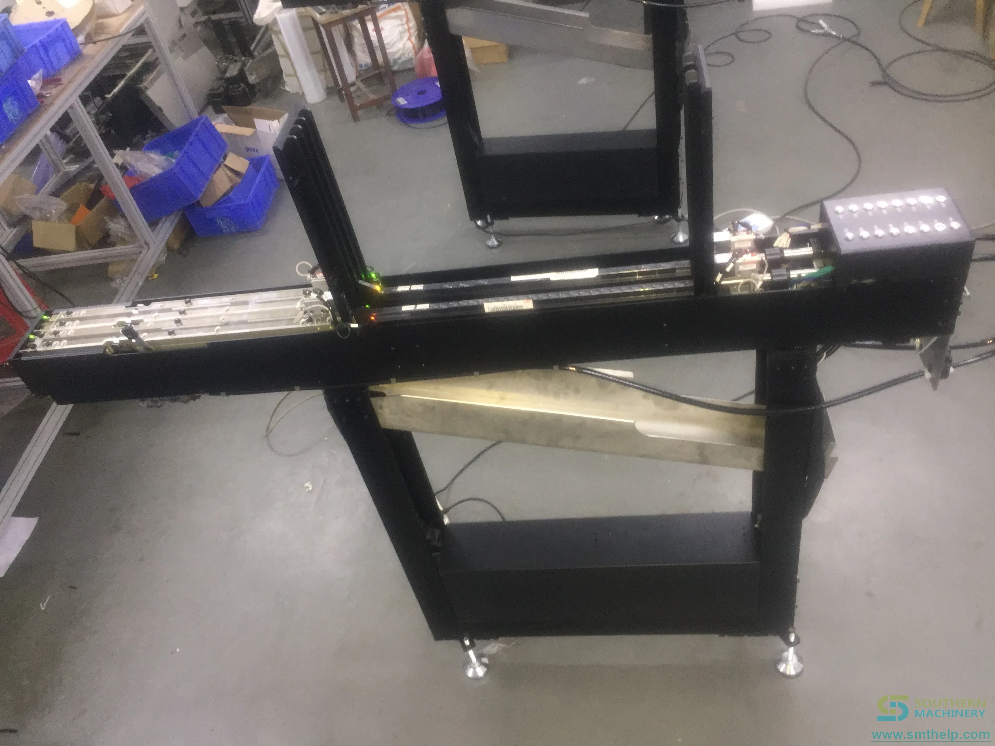
What does tube feeder line integration save per board?
The machine contributes one documented number to this calculation, the 0.8 s feeding speed. Every other input is yours.
Components per board        = tube-fed part numbers counted on the BOM
Manual seconds per board    = components per board x manual seconds per component
Feeder seconds per board    = components per board x 0.8 s (published feeding speed)
Seconds released per board  = manual seconds - feeder seconds
Hours released per month    = seconds released x boards per day x production days / 3600
Payback                     = machine investment / (hours released x loaded hourly rate)
Example arithmetic only: 12 tube-fed components per board, 20 seconds of manual handling per component and the published 0.8 s feeding speed give 240 seconds of manual time against 9.6 seconds of feeder time, so 230.4 seconds released per board. At 300 boards a day and 26 days that is about 499 handling hours a month. The figures are an example, depend on your configuration and part mix, and are subject to final technical confirmation - they are not a performance claim by Southern Machinery. The arithmetic counts handling only: it ignores yield and rework, which favour the machine, and tube and packaging cost, which does not.
How do you commission and keep an integrated feeder running?
The manual describes commissioning as a sequence: mount, air, power, load, adjust, prove.
Six steps from crate to first accepted component
Align the pin holes and seat the positioning key in the plate slot; bring the air on at the higher pressure figure; power up on DC 24 V in the manual's order; load full tubes into the magazine; tune the front and mid-section fibre thresholds with the plus and minus keys, then the cylinder positions, then the baffle width; and prove it by running the acceptance run on your own component rather than the catalogue part.
The shift checklist that prevents most stops
The manual's fault chapter reads as a maintenance schedule: fibre heads cleaned with alcohol; amplifier indicators behaving on a known-present and known-absent component; upper and lower tube sensors responding to a known-empty and known-full position; spring origin and limit groove switches lighting when they should; cylinder movement proven in manual mode at the start of each shift. The wear items are the spring, the tube sensors, the groove switches, the fibre amplifiers and the air cylinders.
How does the STF1003 fit a complete PCB assembly line?
A tube feeder is one station in a full line - SMT placement, reflow, THT insertion, wave soldering, board handling and inspection - sitting with the odd-form and heavy through-hole work before soldering. Matching categories on the Southern Machinery site are feeders, THT machines and SMT machines; the surrounding line is described under the DIP assembly line and one-stop PCB assembly solutions for EMS.
FAQ: tube feeder line integration questions buyers ask
Which machines can the STF1003 be integrated with?
The product sheet lists installations on Panasonic CM602, JUKI, YAMAHA and Mirae odd-form machines, working alongside bowl feeders and radial tape feeders, and states it automates tube-mounted components for SMT machines, non-standard equipment and robotic arm integration.
Do I need a spare feeder interface on the host machine?
No. It runs IO communication over an 8-core 16 mm aviation plug with the component-in-position signal on pin 4, or self-control with no communication at all.
What power and air does the integration need?
DC 24 V, 4 A average and 6 A peak. Air is the unresolved parameter: the sheet gives 0.4 - 0.6 MPa while the manual asks for more than 0.6 MPa, so set the higher figure until your drawing settles it.
What component sizes and tubes are accepted?
Relays, terminals, transformers, square and round capacitors from 3 x 3 x 3 mm to 25 x 25 x 25 mm, in PVC or aluminium tubes with a wall of 0.6 mm or more. The sheet gives a tube length of 200 - 650 mm; the manual narrows it to 300 - 600 mm, and that difference is listed as an open point.
How fast does it feed, and how accurate is the pick?
The published feeding speed is 0.8 s per component, single channel, with four speed gears and a 57-type stepping motor rated to 600 rpm maximum. The published accuracy is plus or minus 0.5 mm, by optical fibre sensing with software compensation rather than a mechanical hard stop.
Can it feed two part numbers at once?
Single channel is standard; dual-channel feeding is listed as a customization for lines that run two tube part numbers together, so it is a configuration question rather than a second machine.
Send the platform, the tube and the sample stick
Integration questions are settled by three things: your host machine model, a sample stick of the component, and a photograph of the part. With those, Southern Machinery can confirm whether the STF1003 can be keyed into your feeder plate, which interface mode fits your IO, and what the changeover looks like when the part mix moves on - including when the honest answer is that the part should stay on tape. Send the details to info@smthelp.com, or start from the product catalogue board.
Comments