
Solder Tin Chip Feeder for SMT Lines by Southern Machinery
A solder tin chip feeder turns standard no-flux tin wire into precisely formed solder chips right at the pick-and-place machine, so the mounter nozzle can add solder volume to pads a stencil cannot fill. The SSPC101 pres
Oct 6, 2026 · Updated Oct 6, 2026 · Southern Machinery
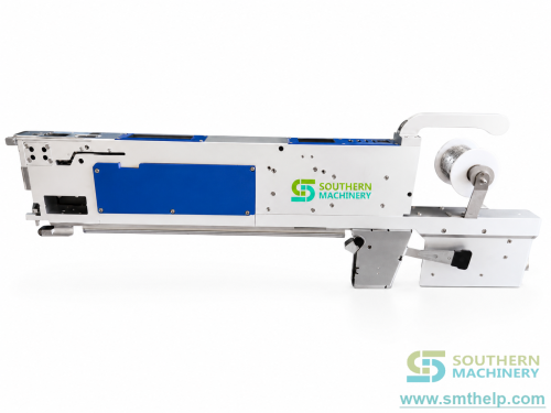
Quick answer. A solder tin chip feeder turns standard no-flux tin wire into precisely formed solder chips right at the pick-and-place machine, so the mounter nozzle can add solder volume to the pads a stencil cannot fill. The SSPC101 presses and cuts the wire on demand with a stepper-driven cam and an air-driven blade, holds ±0.5 mm feeding accuracy with 0.1 s per piece at peak, and occupies one standard tape-feeder slot.
What is a solder tin chip feeder used for on an SMT line?
Solder paste volume is set by stencil thickness multiplied by aperture area: one number for the whole board. Miniaturisation pushed passives down to 0201 while connectors, transformers, battery holders and power inductors stayed large, so one PCB now carries a 0201 resistor next to a 12 mm connector pad that needs several times the solder volume. The stencil serves one world; the other becomes a defect, a stepped stencil or a hand-soldering bench. The SSPC101 adds solder where the stencil starves a pad, using the mounter you already own.
Where the extra solder volume comes from
The document specifies one process instruction: used alongside solder paste, increase the solder volume of the joint. The stencil still prints and the paste still supplies the flux chemistry, while the preform contributes metal volume. The chip lands on the paste-covered pad and both melt in the same reflow profile, adding joint fill and shear strength without a second printing step.
Typical applications
- SMT boards that mix fine-pitch passives with large power pads, connectors, transformers and battery holders.
- Power electronics, LED driver and motor-drive boards where heavy copper draws heat out of a small paste deposit.
- High-mix EMS work where preformed solder reels per product mean MOQ, lead time and dead inventory.
How does the SSPC101 turn tin wire into placed preforms?
Five documented moves take a spool to a placed chip, and all of them happen on the feeder.
Load the wire
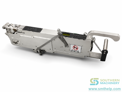
A standard spool of no-flux tin wire mounts on the rear reel holder. The wire diameter sets the chip size, 0.5 mm for 0402 and 2.0 mm for 1510, and any brand of flux-free wire works, which also keeps flux spatter out of the reflow oven.
Feed, press and cut
A stepper motor drives the wire through a precision cam that presses it flat to the target thickness, 0.3 mm at 0402 up to 1.3 mm at 1510. The forming step is pure electric, so there is no hydraulic variation and no warm-up drift, and the air cylinder only drives the cutting blade. Peak output is 0.1 s per piece against a 1.2 s standard pace. The finished chip then waits at the pick position in a known attitude and height, and the mounter nozzle vacuums it exactly as it picks a resistor, within the ±0.5 mm tolerance the vision system expects.
Stencil printing vs solder preforms: which pads need which?
The honest answer is neither instead of the other: the paste wets the pad and the preform adds volume. The document does not present the feeder as a paste replacement.
What the alternatives cost
Manual paste dispensing adds labour and inconsistency. The source states stepped stencils cost 3-5 times a normal stencil and wear quickly under the squeegee, while commercial preformed solder reels carry unit prices and MOQ commitments. The SSPC101 forms chips on demand at 421,000 chips per kg of 0402 wire, so the consumable is priced per kilogram of commodity wire.
SSPC101 solder tin chip feeder specifications
Every figure below comes from the product document and the specification sheet; anything the document leaves open is marked.
- Chip sizes: 0402, 0603, 0603T, 0805, 0805T, 1206, 1206T and 1510, from 1.0 × 0.7 × 0.3 mm to 4.0 × 2.5 × 1.3 mm; custom geometries on request.
- Wire and material: 0.5-2.0 mm wire matched to chip size; material 1-16 mm wide (accessory change for other widths), 0.1-1 mm thick.
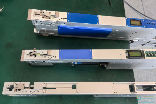
- Footprint: 500 × 36 × 100 mm and 3.5 kg, one standard tape-feeder slot with no extra rail.
- Transfer and cutter: stepper-motor feed with precision cam forming up to 600 rpm/min; air-cylinder blade, the only wearing consumable.
- Utilities: DC 24 V and 0.4-0.6 MPa dry clean air, through one 8-core φ16 mm connector carrying power, ground and IO handshake.
- Speed and accuracy: 1.2 s per piece standard, 0.1 s per piece peak, ±0.5 mm; three consecutive missed feeds raise a feed alarm.
- Yield and compatibility: 421,000 chips per kg at 0402, 7,200 per kg at 1510; YAMAHA, JUKI and SAMSUNG all series, PANASONIC CM/NPM, FUJI XP/NXT and ASM D/H, customisable for any brand and model.
- Not in the source: placement cycle time per board, maximum board size, ambient and noise ratings and field defect statistics. Contact Southern Machinery to confirm these.
How do you integrate a solder tin chip feeder into a complete PCB assembly line?
The feeder is a feeder-bank slot, not a new station, and that is the integration argument.
- Printing: the stencil stays tuned to your fine-pitch components, and the supplement is designed around your stencil and pad list.
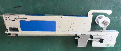
- Placement: the 36 mm body slides into a standard tape-feeder slot and mates with the bank supply, so there is no second table, conveyor or operator station.
- Programming: the solder chip is a component like any other, sharing nozzle, vision and feeder data, so a new pad geometry does not force a new stencil.
- Reflow: flux-free wire leaves the paste to do the chemistry, so fewer spatter deposits reach oven walls, thermocouples and rails.
Where boards continue into through-hole work, SMT-side joints reach wave soldering or a PCB dip assembly line with their full solder volume already placed. Southern Machinery has built SMT and THT assembly, feeding and cleaning equipment in Shenzhen since 2011 and quotes the feeder inside a line project, so start from the one-stop PCB assembly solution overview, the customized feeder family or the machine catalogue.
What is the payback on a solder tin chip feeder?
The source publishes no prices, so payback is a method rather than a quotation: its calculator takes your volumes, your defect rate and your price, and it deliberately excludes the stepped-stencil premium, the preform reel markup, the void escapes that never reach a customer and the oven cleaning cycles skipped because no-flux wire does not spatter.
Rework hours freed per day = solder-chip pads per board x boards per day x manual rework seconds per joint x share eliminated (%) / 3600
Chips placed per month     = solder-chip pads per board x boards per day x working days per month
Annual rework labour       = rework hours freed per day x working days per month x 12 x loaded wage ($/h)
Simple payback (months)    = feeder price / (annual rework labour / 12)
Example only, depending on configuration and subject to final technical confirmation
Two solder-chip pads per board, 300 boards per day, 45 s of manual rework per joint, 80% eliminated, 22 working days per month and a US$12 per hour loaded wage give 600 chips per day and 6.0 rework hours freed per day: about 1,584 hours per year and roughly US$19,000 of annual rework labour addressed. Payback in months is your own quotation divided by that annual figure over twelve. The document publishes no feeder price and no defect benchmark, so run the arithmetic with your numbers.
What does Southern Machinery supply beyond the feeder?
- Free installation and training on mounting, wire loading, chip-size changeover and the three-miss alarm check, taught on your parts and machine.
- Spare parts with a documented one-day lead time for blade, motor and sensor, so a feed fault is a swap, not a schedule change.
- A custom mounter interface where your machine is not one of the six documented brands.
- 7 x 24 support with photo and video diagnostics, plus the wider SMT and THT range and overhaul service.
Solder tin chip feeder FAQ
What solder chip sizes does the SSPC101 produce?
Eight standard sizes, from 0402 at 1.0 × 0.7 × 0.3 mm to 1510 at 4.0 × 2.5 × 1.3 mm, each using a wire diameter between 0.5 and 2.0 mm, and custom geometries on request.
Which mounter brands does the feeder fit?
YAMAHA, JUKI and SAMSUNG all series, PANASONIC CM/NPM, FUJI XP/NXT and ASM D/H are documented, and the feeder is customisable for any pick-and-place brand and model.
How fast does it feed, and how accurate is it?
1.2 s per piece at the standard pace and 0.1 s per piece at peak, with up to 600 rpm motor speed and ±0.5 mm accuracy. Line throughput is set by the mounter placement cycle, not the feeder.
What happens when the tin wire runs out?
A material sensor watches the pick position, and three consecutive missed feeds raise a feed alarm on the mounter, defined in the document as a process interlock rather than a warning.
What utilities does it need?
DC 24 V for the motor and sensor, and 0.4-0.6 MPa dry clean compressed air for the cutter, delivered through one 8-core φ16 mm connector. No external supply and no software licence.
Do I need special tin wire?
No: any brand of no-flux tin wire works if the diameter matches the chip size. Alloys such as SAC305 or Sn63Pb37 form slightly different dimensions, which the forming accessory and cut length compensate for.
Tell us the pad. We will tell you the chip.
Send your stencil design, the pads that need extra solder volume, your mounter model and your alloy: Southern Machinery returns a feeding evaluation with the recommended chip size, wire consumption estimate and a configuration to price, at info@smthelp.com or WhatsApp +86 13602562576. Background reading: the solder wire feeder versus preform cost comparison, the SMT machine range and the customized feeder family.
Comments