
SMT Line Layout Guide by Southern Machinery
A single-lane SMT line layout uses PCB handling modules to move boards between printing, placement, inspection and soldering stages without manual transport. Southern Machinery combines a PCB loader, link conveyor, unloader, NG/OK buffer and PCB flipper within one board-flow concept, with the loader specified as compatible with the standard SMEMA interface. Buyers should confirm board flow, machine interfaces, floor space and transfer requirements before selecting modules. The goal is continuous board handling, safer transfers and fewer manual interruptions, while final capacity and configuration depend on the complete line and require technical confirmation.
Oct 17, 2026 · Updated Oct 17, 2026 · Southern Machinery
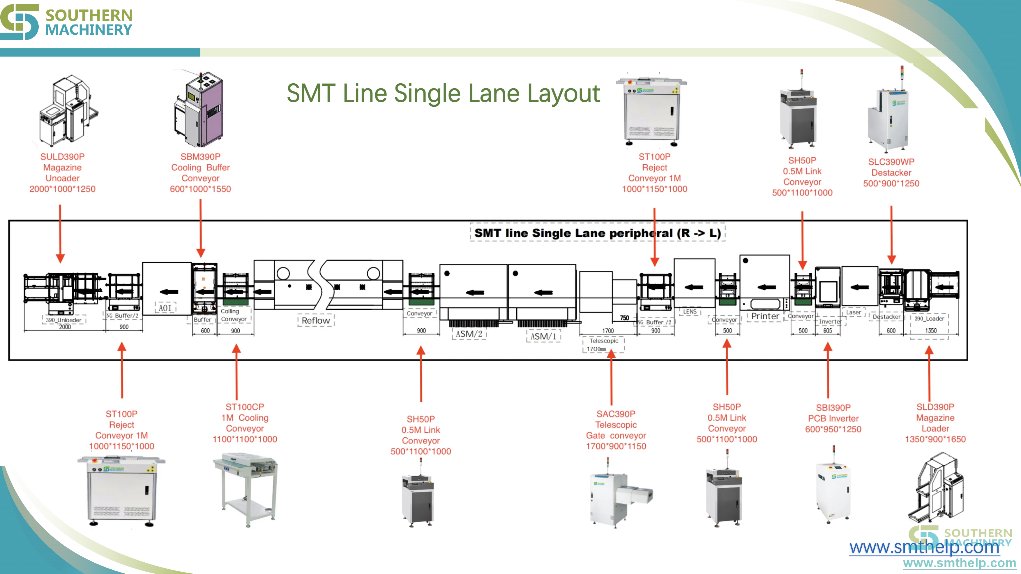
A single-lane SMT line layout uses PCB handling modules to keep boards moving from loading, through processing and inspection, to unloading. Southern Machinery brings a PCB loader, link conveyor, PCB unloader, NG/OK buffer and PCB flipper into one integrated board-flow concept for electronics manufacturing lines.
The purpose is straightforward: reduce manual board transport and make the transfer between production stages consistent. The source page identifies the loader as compatible with the standard SMEMA interface. It also presents integrated line solutions tailored to a plant's production requirements.
What is an SMT line layout used for?
An SMT line layout organizes PCB handling equipment around the sequence in which a board moves. It defines where boards enter, how they transfer between stages, where they are buffered, whether they are turned over, and how they leave the line. Southern Machinery describes this peripheral range as equipment designed for seamless integration and efficiency around printing, placement, inspection and soldering.
Typical production scenarios
This concept is relevant to EMS, ODM, automotive-electronics, medical-electronics and industrial-control teams moving a PCB family through several process steps. Evaluate it when boards are carried between machines, flipped by hand for a second side, or sorted manually after inspection.
Why does an SMT line layout start with board flow?
Board flow is the common path through the line. A board can wait in a loader rack, move on a conveyor, be processed, queue in a buffer, turn for a second side, or be stacked by an unloader. Listing these states exposes manual interventions before equipment is ordered.
The layout should match the real product mix
The source establishes the module functions but does not specify a universal board-size range, line speed, conveyor length or throughput figure. Those values are not specified in source — contact Southern Machinery to confirm against the actual board family and complete line.
Which PCB handling modules belong in a single-lane SMT line?
Start with the minimum modules required by the physical flow, then add buffering or turning only where the process needs it.
PCB loader: start the transfer
The PCB loader automatically feeds PCBs into the production line and is intended to support a consistent, uninterrupted workflow. The source specifically identifies standard SMEMA-interface compatibility for the loader.
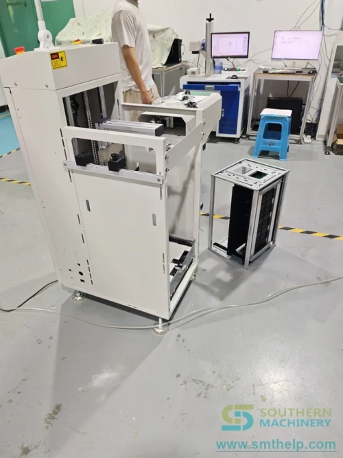
Confirm loader format, interface, board family and hand-off direction for the proposed configuration.
Link conveyor: bridge process stages
The link conveyor connects different SMT stages and provides transport between machines. Its placement should follow the process sequence and physical distance between stages.
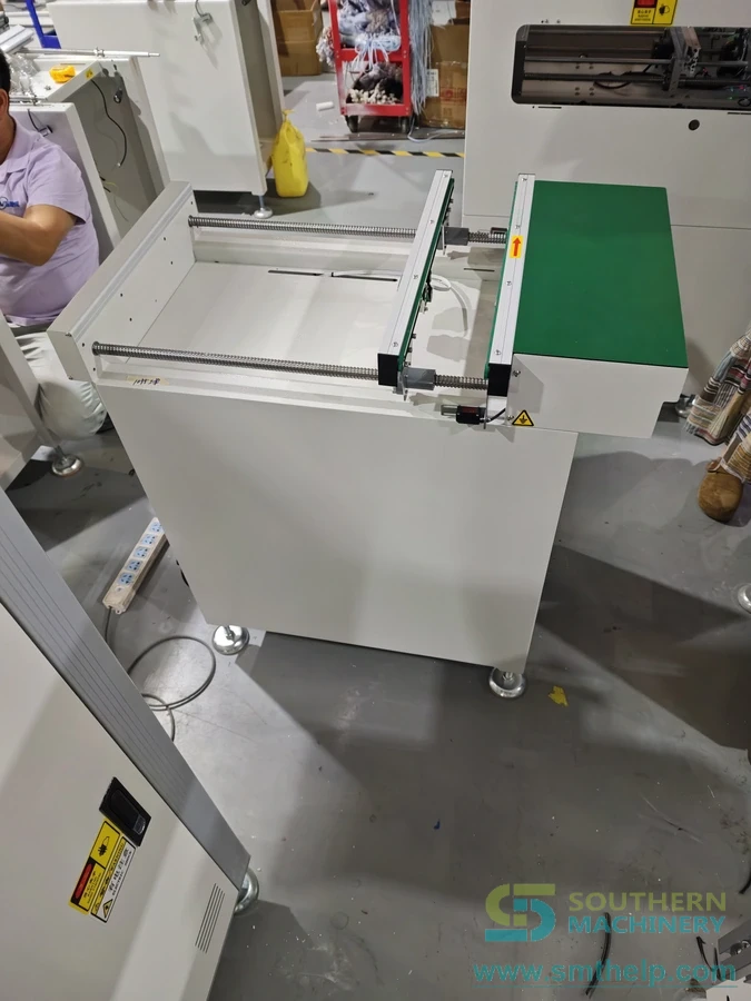
Conveyor length, transfer mechanism, rail adjustment and line-height requirements are not specified in the source; treat them as configuration questions.
PCB unloader: close the transfer loop
The PCB unloader safely receives and stacks assembled PCBs at the end of the line, ready for the next process.
NG/OK buffer: separate post-inspection flow
The NG/OK buffer intelligently sorts and buffers good and rejected boards after inspection, creating a defined destination for both states.
PCB flipper or inverter: support double-sided assembly
The PCB flipper or inverter turns boards for double-sided assembly while maintaining production flow without manual intervention. Include it when the route requires a side change.
Manual board transfer vs automated board handling: what changes?
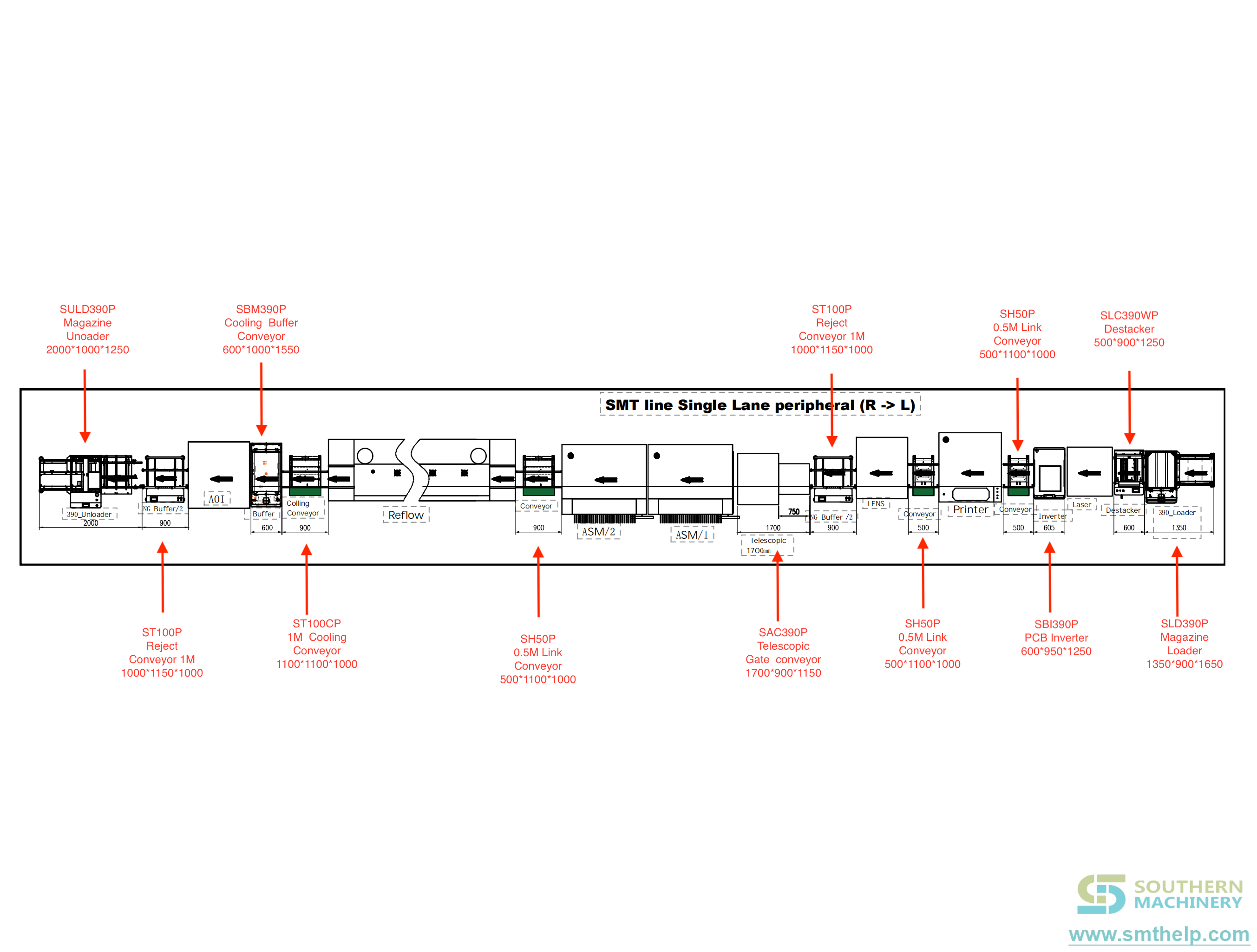
Manual transfer can suit low-volume prototype work, but it adds a person, a walking route and a hand-off to the process. Automated handling creates a repeatable physical path: the loader supplies boards, conveyors link stages, the buffer sorts after inspection, the flipper turns boards, and the unloader stacks output. The value comes from connecting these functions, not adding disconnected equipment.
How does the layout connect to a complete PCB assembly line?
Use the board-flow sequence to map the complete line. A practical structure is: PCB loader → link conveyor → process equipment → inspection → NG/OK buffer → optional PCB flipper → PCB unloader.
The exact order depends on the product route. Review the broader board handling system category and compare it with the complete machine catalog when drafting the line concept.
Interface questions to settle before purchase
- Which line direction and machine sequence will the layout follow?
- Which loader interface and hand-off method are required?
- What PCB sizes, weights and edge clearances must the transfer path accept?
- Which conveyor lengths are needed between process machines?
- Is an NG/OK buffer required after inspection?
- Does the route require a flipper or inverter for a second side?
- What output format should the unloader provide?
- What site power, air, floor-space and safety conditions apply?
Where the source does not provide a value, the answer should be marked as not specified in source — contact Southern Machinery to confirm for the proposed configuration.
What does an SMT line layout cost, and how can ROI be framed?
Do not price the layout as a row of isolated machines. The decision should include the modules, integration work, floor space, utilities, installation, training, spare-parts planning and the cost of the manual activity displaced.
A simple planning equation is:
Annual avoidable manual-transfer hours = boards per day × manual transfers per board × seconds per transfer × production days ÷ 3,600
Example only: if a line processes 800 boards per day, with one manual transfer per board taking 10 seconds, across 200 production days, the calculation is 800 × 1 × 10 × 200 ÷ 3,600 = 444.4 hours per year.
This is an illustrative calculation, not Southern Machinery performance data or a promise of financial return. Actual value depends on configuration and the complete process, and is subject to final technical confirmation.
Validate the manual transfers actually removed, labour rate, floor space, installation scope and maintenance plan. Do not treat labour avoidance as the only benefit; consistent transfer and defined NG/OK handling may also affect line operation.
How does board handling affect quality and throughput?
The source supports a specific quality mechanism: the NG/OK buffer sorts and buffers boards after inspection. It also describes smooth and safe conveyor transport and flipper operation without manual intervention. Those functions make board state and movement more structured.
Decide which inspection result triggers OK or NG routing, how buffered boards are released, and how output is identified. The source does not specify defect rate, yield improvement or inspection accuracy.
The source does not state line throughput, conveyor speed, cycle time or capacity. Do not transfer a figure from another machine; ask for the compatible speed and buffering requirement based on the actual process equipment.
How should maintenance and training be planned?
Request a maintenance schedule, recommended spare-parts list and operator training scope with the final configuration. Maintenance intervals and consumable life are not specified in source and must be confirmed.
What should an SMT line-layout RFQ include?
Provide the board family, process sequence, line direction, floor dimensions, buffer and flipper requirements, output format, utilities, operating pattern and existing machine data. Add photographs or a dimensioned sketch.
Southern Machinery, founded in Shenzhen in 2011 and serving 237+ global customers, focuses on SMT and THT PCB assembly automation. Its complete-line capability spans SMT, THT, wave soldering, board handling and inspection, with high-efficiency, cost-effective, global service, spare-parts support and professional training as stated positioning.
FAQ
What is an SMT line layout?
It is the arrangement and connection of process and PCB handling equipment along the route a board follows from loading to unloading. It defines transfers, process order, buffering, turning and output.
Which modules does this single-lane layout include?
The source presents a PCB loader, link conveyor, PCB unloader, NG/OK buffer, PCB flipper or inverter, and integrated line solutions.
Is a buffer always required?
Not necessarily. A buffer is most clearly justified when the process needs a defined holding point or NG/OK separation after inspection. The source presents it as a module, not a mandatory part of every line.
Can the layout handle double-sided assembly?
The PCB flipper or inverter is presented for double-sided assembly and for maintaining production flow without manual intervention. Confirm the exact board route and handling requirements for the proposed configuration.
What speed or capacity can I expect?
No line speed, capacity or throughput figure is specified in the source. Contact Southern Machinery to confirm performance against the complete configuration and final technical requirements.
Next step: review the board handling system
Start with the Southern Machinery board handling system, then send the product route, board family and floor constraints for a configuration review. The machine catalog provides another way to review the wider equipment range before the final line layout is confirmed.
Comments