
SMT Glue Printing and SMD Adhesive Dispensing for Bottom-Side PCB Assembly
SMT glue printing and adhesive dispensing hold bottom-side SMDs in place through wave soldering. Learn the dot, stencil, and cure parameters that decide yield.
Sep 20, 2026 · Updated Sep 20, 2026 · Southern Machinery
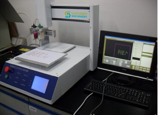
SMT Glue Printing and SMD Adhesive Dispensing for Bottom-Side PCB Assembly
Wave-soldered assemblies still need something to hold bottom-side SMDs in place before the boards reach the solder wave. That "something" is surface-mount adhesive — and whether you print it through a stencil or dispense it with a robot determines your missing-component rate, your line layout, and your cure profile. This guide covers both routes and the process parameters that actually drive yield.
<iframe width="560" height="315" src="https://www.youtube.com/embed/CJ0w8yRnNIc" title="SMT glue screen printing" frameborder="0" allowfullscreen></iframe>
What is this machine used for?
SMT glue printing — also called adhesive printing, glue screen printing, or chipbonder printing — deposits a controlled dot of surface-mount adhesive onto the PCB through a stencil aperture, using the same stencil-printing platform that applies solder paste.
The adhesive is later cured into a mechanical joint that holds bottom-side chip components against gravity, placement vibration, and the turbulence of the solder wave. Without it, chip capacitors, resistors, SOTs, and small ICs on the wave-solder side will float off or shift during wave soldering.
Put simply: SMT glue printing attaches bottom-side surface-mount components to the board before wave soldering, so a mixed-technology assembly (SMD on the bottom, THT on the top) can be soldered in a single wave pass without losing parts.
Print or dispense? Choosing the right adhesive process
Two production routes are used, and both are valid depending on your board mix:
1. Stencil printing of adhesive. The adhesive is printed through a dedicated glue stencil on a screen printer — the same class of platform used for solder paste. This is the fastest route for high-volume boards with a stable layout, because an entire panel receives adhesive in one print stroke. It is the process shown in the video above.
2. High-speed dispensing of adhesive. A dispensing robot places individual dots, programmed point by point, which suits high-mix production, odd board shapes, and the demanding case where adhesive must be dispensed between solder-pasted pads on the same side of the board.
Where both solder paste and adhesive are required on the same side, the sequence matters: print the solder paste first, then dispense the adhesive between the pasted pads before placement. This mixed process is used to cut defects such as missing components and insufficient solder joints, and it works for both double-sided reflow SMT and mixed SMT/THT assemblies.
<iframe width="560" height="315" src="https://www.youtube.com/embed/KoqXdWuV2Mc" title="Auto SMT Glue screen printing for Electronic Manufacturing PCB assembly" frameborder="0" allowfullscreen></iframe>
SMD adhesive dot geometry: the parameter that decides yield
Most bottom-side component loss traces back to dot shape, not to the machine. The engineering targets below come from Southern Machinery's own process guidance for adhesive deposition between solder-pasted pads:
- Dot shape: a tall, cylindrical dot with minimal slump. A triangular "Hershey kiss" profile often cannot reach the component body above the solder paste deposit, and missing components appear after the wave.
- Dot height: typically about half the dot diameter. If the dot cannot be taller than the paste deposit plus the pad finish, the adhesive never touches the component.
- Dot diameter vs. pad spacing: pad spacing is tighter on boards designed for solder paste (about 0.020" between the pads of an 0603 chip) than on boards designed for adhesive (about 0.040"). A 0.030" dot suits an adhesive-designed footprint, but the same board laid out for paste needs roughly a 0.015"–0.018" dot.
- Board finish and stencil thickness: a typical HASL finish is about 0.003" thick, and a paste stencil is often 0.006"–0.007". The dot must be tall enough to clear both and still contact the component.
- Adhesive rheology and green strength: the material must resist slump and hold the component before cure. Heat lowers viscosity and encourages slump, so heated dispensing makes stable dot height harder to achieve.
- Nozzle selection (dispensing): nozzle ID is roughly half the required dot diameter. Standoff style — castle, post, or dual post — sets the gap between the tip and the board. For adhesive dispensed between solder-pasted pads, a single-post nozzle is normally the right choice, positioned at 45°, 135°, 215°, or 315° around the pad circuitry.
- Placement accuracy: with paste alone, reflow forces self-centre the component on its pads. Cured adhesive resists those forces, so the placement machine's accuracy and repeatability matter more in a glue process than in a pure paste process.
Typical bottom-side line configurations
Traditional bottom-side line: adhesive dispenser → chipshooter → cure oven → wave soldering → inspection and rework. Simple, reliable, and driven almost entirely by the adhesive's green strength and post-cure strength.
Bottom-side line with solder paste: stencil printer (paste) → high-speed adhesive dispenser → chipshooter → reflow/cure oven → wave soldering → inspection and rework. This configuration adds solder paste to the bottom side, which increases joint strength and reduces missing-part defects and wave-soldering problems such as insufficient solder — at the cost of more process control.
Either way, the line must be considered as a whole. Stencil design, nozzle design, dot height, cure profile, and placement capability all interact, and changing one of them changes the others.
Adhesive curing: the profile that protects the wave
When solder paste and adhesive are both present, the cure cycle is a shared profile, not a separate step:
- Target a 150 °C bondline temperature, and verify it with thermocouples at several points on the assembly.
- Hold at approximately 150 °C for about 90 seconds before ramping to the reflow temperature.
- Avoid bondline temperatures above 160 °C — the adhesive can become brittle and components can be lost in the solder wave.
- Validate the actual solder joints produced by the combined profile, not just the adhesive cure.
Key selection parameters
When specifying glue printing or adhesive dispensing equipment, confirm these points with your supplier rather than assuming defaults:
- Adhesive type and rheology — dot profile, slump behaviour, and green strength required by your component mix
- Board and panel size range, plus the maximum and minimum PCB thickness the conveyor or platform must handle
- Printing or dispensing volume — whether the production mix justifies a stencil-print step or needs programmable dispensing
- Dot size range and repeatability required by your smallest footprint
- Line integration — SMEMA-compatible inline connection versus a standalone offline cell
- Cure strategy — dedicated cure oven or a combined cure-and-reflow profile
- Facility requirements — power supply, air supply, and operating environment
Equipment support from Southern Machinery
Southern Machinery supplies the equipment around the adhesive process as part of a complete SMT/THT line:
- Stencil printing platforms — semi-automatic and fully automatic screen printers (SP series) for solder paste and stencil-based adhesive printing, with tooling advice for glue stencils.
- Programmable dispensing robots — for high-mix adhesive deposition. The standard dispensing platform offers a 310 × 330 × 60 mm X/Y/Z work area, up to 500 mm/sec movement speed, ±0.01 mm repeatability, 3-axis interpolation, belt and precision linear guide transmission, micro-stepping motor drive, touch-screen or computer programming with 16 inputs and 16 outputs, AC 220 V / 300 W power, and a 670 × 550 × 610 mm footprint.
- Curing and reflow ovens — for the combined adhesive-cure and solder-reflow profile described above.
- Wave soldering machines — including lead-free and nitrogen-capable models for the final bottom-side joint formation.
- Inspection and rework — AOI and rework stations downstream of the wave.
For the demanding case where adhesive must be deposited between solder-pasted pads, Southern Machinery also covers the nozzle and tooling side of the process, which is often where yield is won or lost.
Typical application scenarios
Glue printing and adhesive dispensing matter most in factories running wave-soldered, mixed-technology boards:
- EMS and contract manufacturers with high board mix and frequent changeover
- Automotive electronics — control boards, power modules, and sensor assemblies with bottom-side chip components
- LED lighting and drivers — LED bulb, tube, and driver PCBs with bottom-side SMDs
- Power supplies and adapters — vehicle power supplies, energy-saving power supplies, and ballasts
- Home appliance control boards — air conditioner, TV, microwave, electric kettle, and induction cooker PCBs
- Industrial control and instrument boards — where a missing component means a field failure
How it integrates into a complete SMT/THT PCB assembly line
An adhesive process sits inside the bottom-side flow, not beside it. A typical mixed line runs: bare board loading and handling equipment → stencil printer for paste and/or adhesive → glue dispenser where dispensing is required → chipshooter or pick-and-place → reflow/cure oven → board handling and buffering → wave soldering → lead cutting → cleaning → AOI and rework → unloaders and magazine handling.
Because Southern Machinery builds SMT placement, THT insertion, wave soldering, board handling, cleaning, and inspection equipment, the adhesive stage can be specified together with the rest of the line — including SMEMA interfaces, conveyor widths, and board-transfer heights — instead of being retrofitted later.
ROI, quality, and throughput perspective
- Missing components after the wave are the single most expensive defect in a bottom-side process: they are usually detected only after soldering, and rework means manual re-soldering on a completed board. Correct dot geometry, green strength, and cure profile remove most of them at the source.
- A stencil-print adhesive step replaces a slow, per-point dispensing pass on high-volume boards, freeing dispenser capacity for the boards that genuinely need programmable deposition.
- Combining paste and adhesive on the bottom side raises joint strength and reduces insufficient-solder problems in the wave, which pays back in first-pass yield rather than in scrap.
- Parameter discipline compounds — dot shape, nozzle selection, and cure profile are one-time engineering decisions that keep paying out on every board that follows.
FAQ
What is SMT glue printing used for?
It applies surface-mount adhesive to the bottom side of a PCB so that SMD components stay attached during wave soldering. It is standard in mixed-technology assemblies that combine bottom-side SMDs with through-hole parts.
Should I print adhesive through a stencil or dispense it?
Print through a stencil for high-volume boards with a stable layout, and dispense for high-mix production, unusual board shapes, or where adhesive must go between solder-pasted pads. Many factories run both.
Can the same screen printer apply solder paste and adhesive?
Adhesive printing uses the same stencil-printing principle as solder paste, with a dedicated glue stencil and the appropriate tooling. Confirm the specific printer configuration and stencil design with your equipment supplier for your board mix.
What cure profile does SMD adhesive need?
For adhesive deposited between solder-pasted pads, target a 150 °C bondline temperature verified with thermocouples, hold for about 90 seconds before ramping to reflow, and keep the bondline below 160 °C so the adhesive does not become brittle.
Why do components fall off during wave soldering?
Usually because the adhesive dot did not contact the component body — often a slumped dot, a dot too small for the pad spacing, or excessive heat lowering adhesive viscosity. Dot shape, nozzle ID, and cure profile are the first things to check.
What support does Southern Machinery provide?
Southern Machinery supplies SMT/THT equipment and line solutions, spare parts, retrofit and upgrade kits, training and repair services, with global after-sales support. Configuration advice is available before you buy.
Contact Southern Machinery for configuration advice
Tell us your board mix, bottom-side component list, and line layout, and we will recommend an adhesive printing or dispensing configuration that fits your existing SMT/THT line.
- Email: jasonwu@smthelp.com
- Phone / WhatsApp: +86 13602562576
- Machine catalogs and files: https://file.autoinsertion.com
- Machine photos: https://ph.smthelp.com
- Website: https://www.smthelp.com
Southern Machinery — Shenzhen, China. Founded 2011. SMT and THT PCB assembly automation equipment and full-line solutions, serving 237+ customers worldwide.
Comments