
Preparation of SMT Equipment Before PCB Board Insertion: The Pre-Flight Checklist for Precision THT Assembly | Southern Machinery
Equipment preparation is the part of PCB assembly that decides whether an insertion cell is repeatable. This guide covers the pre-flight routine for THT and odd-form insertion machines: mechanical and structural checks, feeder loading and calibration, insertion-head debugging, software parameters taken from the PCB design data, material screening for tape-reel components, and first-article verification. Includes documented reference platforms - S-3010B and S3000 radial inserters, S-70LD odd form, S7020 / S-7000E / S-7000T terminal insertion - plus typical applications, full-line integration, key selection parameters and the ROI case. Southern Machinery, Shenzhen, China, founded 2011, 237+ global customers.
Sep 26, 2026 · Updated Sep 26, 2026 · Southern Machinery
Preparation of SMT Equipment Before PCB Board Insertion: The Pre-Flight Checklist for Precision THT Assembly
A THT or odd-form insertion cell does not fail because the machine is slow. It fails because something was not confirmed before the first board went in — a feeder index that sits one pitch out, an insertion head that picks a fraction of a millimetre off centre, a clinch anvil set for the wrong lead span, a parameter set copied from the last program without being re-verified against the current BOM. Every one of those defects is recoverable at the setup bench and expensive on the line.
This guide follows the preparation sequence shown in Southern Machinery's demo video Preparation of SMT Equipment Before PCB Board Insertion: The Key to Precision Manufacturing, and turns it into a practical pre-flight routine for SMT and THT line engineers. Southern Machinery has been building insertion, board-handling and wave soldering equipment in Shenzhen, China since 2011 and currently supports 237+ customers worldwide, so the checklist below is written the way we see customers actually commissioning a cell.
<iframe width="560" height="315" src="https://www.youtube-nocookie.com/embed/ngJkUbM3csw?rel=0" title="Preparation of SMT Equipment Before PCB Board Insertion | Southern Machinery" frameborder="0" allow="accelerometer; autoplay; clipboard-write; encrypted-media; gyroscope; picture-in-picture" allowfullscreen></iframe>
Source video: Preparation of SMT Equipment Before PCB Board Insertion — @Smthelping (Southern Machinery), Product demo, 3:03.
What is this machine used for?
The machine in the video is a THT automatic insertion machine — a radial, odd-form or terminal inserter that places leaded components into plated through-holes on a mixed-technology PCB. But the video is really about the ninety minutes before insertion starts, and that is the part buyers underestimate when they compare quotations.
In practice, "preparation" means proving four systems at the same time:
- Mechanical structure and transport. The frame, the X-Y table or positioning head, the conveyor rails and the board-support/clinch tooling must be stable and aligned. If the structure is not stable, nothing downstream is repeatable — you will chase positional drift all shift instead of producing boards.
- Feeders. Feeders are calibrated and then set with the spacing, index and cover-tape tension that matches the actual component tape on the reel, so that a component arrives at the pick position at the same coordinates for every cycle. In the video description Southern Machinery puts it directly: the feeders are set with appropriate spacing and tension according to the specification of the boards, in order to supply components precisely.
- Insertion / placement heads. The head is debugged and checked for pick height, tool concentricity and Z-axis travel so that it guarantees accurate positioning and smooth transport of the board through the cell.
- Software parameters. Coordinates, insertion angles, placement/insertion pressure and speed are configured from the PCB design data — not from memory — which is what keeps placement accuracy inside a micrometer-level tolerance band rather than "close enough".
Only after those four are signed off does the machine run: the boards are transported, positioned and identified by the vision/mark-point system, and the heads pick and insert at production speed. In the demo, a complete insertion cycle is described as running at 1.5 to 2 seconds — a useful reference figure for takt planning, though the real number on your line depends on component count, lead spans and the machine model you select.
The buyer-facing summary: you are not purchasing "an inserter". You are purchasing a repeatable insertion result, and the preparation routine is the part of the purchase that determines whether you get it.
The pre-flight preparation checklist
Run this as a documented routine, not as tribal knowledge. Each row has a pass criterion, and the routine is signed off before the first production board is loaded.
| # | Step | What to verify | Pass criterion |
|---|------|----------------|----------------|
| 1 | Power and safety | Fixed supply of the rated voltage/frequency, separate reliable grounding to the ground bus, emergency-stop location known and clear | No unsafe factor around the machine; guards and E-stop functional |
| 2 | Mechanical structure | Frame levelling, conveyor rail parallelism and height, board-support and clinch tooling condition | Structure stable; rails parallel; no play in tooling |
| 3 | Conveyor / board handling | Rail width set to the actual PCB width and thickness; SMEMA handshake with upstream and downstream stations | Board transfers without skew, jam or edge damage |
| 4 | Feeder loading and calibration | Correct reel per part number; tape path; index engagement; cover-tape peel tension; pick position and pick height | Dry cycles produce a component at the same pick coordinates every cycle |
| 5 | Insertion head / tooling | Pick height, tool concentricity, Z travel, nozzle or gripper condition and cleanliness | No visual offset at pick and place; no tool wear marks |
| 6 | Program data | Program revision matched to the current BOM and PCB revision; coordinates, insertion angle, pressure and speed loaded from design data | Program file is a controlled document, not an unsaved edit |
| 7 | Vision / mark-point | Mark-point teaching or verification on the actual board artwork; calibration current | Board identified and zeroed consistently across a 3-board trial |
| 8 | Material preparation | Tape-reel components screened and inspected — capacitors, inductors, terminals — for size, lead form and performance against the BOM | Rejected material segregated; no mixed-reel feeders |
| 9 | First article | Insert a first board, verify position, angle, seating depth and clinch on every unique component | First article signed; deviations fed back into program or tooling |
| 10 | Traceability record | Setup sheet, program revision, material lot and first-article result recorded against the work order | Record retrievable for the batch |
Steps 8 and 4 are the ones most often skipped, and they are the two that create failures you cannot see at the insertion station. Mixed or out-of-tolerance reel material, and feeder spacing or tension that is "near enough", both produce components that are placed — and only fail later as bent leads, floating parts or opens after wave soldering.
Typical applications
Automatic insertion preparation pays off wherever a board carries a stable set of leaded parts at volume. Five representative scenarios:
- Home appliance control boards — radial capacitors, transistors and key switches on air-conditioner, induction-cooker, microwave and appliance control PCBs, where the same radial part family repeats across many models.
- Power supply and adapter boards — bulk radial capacitors, inductors and screw/plug terminals; terminal insertion with a disciplined pre-flight routine is what prevents the intermittent contact faults that customers discover in the field.
- LED lighting driver boards — radial electrolytic capacitors, leaded LEDs and key switches on drivers and luminaire control boards, including long or narrow board formats.
- Automotive and vehicle electronics — connectors, terminals, relays and odd-form parts on car audio, vehicle power supply and control modules, where first-article control and traceability are non-negotiable.
- New energy, instruments and power-tool boards — odd-form parts such as transformers, relays, fuse holders, terminal blocks and MOS connectors that cannot be tape-packed for a conventional radial inserter, handled on an odd-form platform with vision-based polarity checks.
In all five, the preparation routine is the same; only the tooling, feeder set and program change.
How it fits into a complete PCB assembly line
Preparation is a gate in the line, not a standalone activity. A typical mixed-technology line runs:
SMT block → screen printer → SPI → pick-and-place (chip mounter) → reflow → AOI → THT insertion block → radial insertion (S-3010B / S3000) → odd-form insertion (S-70LD) → terminal and PIN insertion (S7020 series / S-7000E / S-7000T) → wave soldering (S-WS450 / S-WS350B lead-free dual wave) → cleaning (SME-6200 / S1688 stencil and PCBA cleaning) → inspection and test (AOI, SPI, X-ray) → board handling (SLD250 / SUL250 magazine loader and unloader, conveyors) → MES/traceability.
Two consequences matter for the buyer:
- Each handover is a preparation event. The SMEMA interface only passes a board if rail width, height and handshake are correct at both ends. A perfectly prepared inserter feeding an unprepared conveyor still produces scrap.
- Insertion preparation is upstream of soldering, so errors are discovered late. A terminal inserted one pitch out, or a radial part seated 0.5 mm high, may pass insertion inspection and only fail at wave soldering or final test. That is why the pre-flight routine includes feeder calibration and material screening explicitly, and why the first-article step belongs to the process, not to the operator's discretion.
Complementary stations in the same ecosystem — flux/selective soldering cells, conformal coating, depaneling, reel scrap tape cutting and X-ray component counting — all follow the same discipline: verify the setup, then release production.
Key selection parameters
When you specify an automatic insertion platform, these are the parameters that decide whether the preparation routine you just read about is workable on your product mix. Published figures are from the respective Southern Machinery product pages; always confirm the datasheet for your exact configuration.
| Parameter | Why it matters in preparation | Documented reference values (vendor-published) |
|-----------|------------------------------|------------------------------------------------|
| Insertion head count | More heads = more feeders and tools to calibrate per setup, but higher throughput | 1–4 heads optional on terminal platforms; S-70LD odd form: 4 heads |
| Rated vs actual speed | Rated CPH is a mechanical maximum; plan takt on realistic throughput | S3000 radial: up to 18,000 CPH max, approx. 10,000 CPH typical; S-3010B: 22,000 CPH rated / approx. 13,000 CPH actual; S-70LD: 4,000 CPH (3,800 CPH radial resistor) |
| Lead spans / component range | Determines which clinch tooling and feeder set you need per product | Radial: 2.5 / 5.0 mm dual span (S3000); 2.5 / 5.0 / 7.5 / 10.0 mm (S-3010B); odd form: 3×3–30×30 mm, up to 50 mm high |
| Insertion angle resolution | Affects program data and polarity-critical parts | 0–360° adjustable in 1° increments |
| Positioning / accuracy class | Drives first-article frequency and rework rate | S-70LD: ±0.05 mm, vision-guided; terminal platforms: 0.001 mm/pulse, vertical error ≤0.8° |
| PCB size and thickness envelope | The rail width and support tooling must cover your whole product mix | S3000: 50×50–400×380 mm, 0.79–2.36 mm; S-3010B: up to 400×400 mm, 0.79–2.36 mm; S-70LD: 50×50–300×300 mm, 0.8–5.0 mm; S-7000E: up to 480×390 mm, 0.76–2.36 mm |
| Feeder and feeding method | Feeder calibration is the highest-risk preparation step | Tape, vibration plate or bowl, or reel — model dependent |
| Clinch method | Determines anvil tooling and post-insertion reliability | Inward / outward / "N" type clinch, model dependent; clinch length 1.5–2.2 mm, clinch degree 10–35° on the radial platform |
| Program and data interface | How fast a new product is prepared and how it is controlled | Offline programming; USB/Excel data input; PC control with vision calibration |
| MES / traceability interface | Turns the preparation record into an auditable document | RS-232C to MES on the S-7000T terminal platform; insertion verification via electrical continuity or pin-penetration sensing with QC data on the system PC |
| Utility requirements | Site readiness before installation (not after) | Typical: 220 V AC 50/60 Hz; air 0.4–0.6 MPa; ambient 10–35 °C — confirm per model |
| Inline vs offline configuration | Whether the cell has to handshake with the line | Inline SMEMA on the odd-form platform; offline standalone is a valid choice for low-volume or high-mix work |
| Tooling and feeder support | The long-term cost of new product introduction | Availability of custom nozzles, grippers and feeder tracks, and of spare-part support |
ROI and quality perspective
From the buyer's side, preparation discipline is one of the highest-return investments in a THT line, because it attacks three cost pools at once.
Rework. A mis-seated or wrongly oriented inserted part is not discovered at the insertion station — it is discovered after wave soldering or at final test. Every board that reaches that point carries the full accumulated cost of the line plus the touch time to diagnose and repair. A ten-step pre-flight routine is a fraction of the cost of one rework campaign.
Yield loss and scrap. Insertion force set too high, or a feeder indexing one pitch out, damages components and the plated through-hole barrel. Hole and lead damage is often not repairable, so the loss is a whole board, not a part.
Capacity and changeover. Time spent re-running a program because the parameter set was not verified against the current BOM is pure lost capacity. On a cell that runs multiple product variants per week, the preparation routine is what makes a fast changeover fast and clean — the alternative is to gain setup minutes and pay them back in rework hours.
On the quality side, the reproducible part matters more than the nominal part. A prepared cell produces the same cycle at board 1 and board 5,000, which is what allows you to reduce inspection sampling, hold a stable first-pass yield and give your customer a traceable process record. That is also the practical reason to pair the machine with insertion verification and MES logging: the setup sheet, program revision and first-article result become evidence, not memory.
Southern Machinery's positioning is deliberately unglamorous here — we build the insertion, handling, soldering and cleaning stations, and we help customers build the routine around them, backed by an after-sales ecosystem of spare parts, retrofit kits, repair, overhaul and operator training.
FAQ
What is meant by "preparation of SMT equipment before PCB board insertion"?
It is the setup and verification routine carried out on an insertion machine before the first production board is loaded: mechanical and structural checks, conveyor and board-support setup, feeder loading and calibration, insertion-head debugging, software parameter configuration from the PCB design data, material screening, and a first-article verification. Only then is the cell released to run.
How long does preparation take, and does it need a specialist?
It depends on the number of unique components, feeders and tooling changes in the program. The mechanical, feeder and head checks are operator-level tasks once the routine is documented; program data, vision/mark-point verification and first-article sign-off are normally engineering-level. The point of writing the checklist down is that you do not need a specialist for a repeat setup.
What happens if the feeders are not calibrated before insertion?
The component arrives at the pick position slightly off in pitch, position or angle every cycle. The machine still inserts — which is why it is dangerous — but you get bent leads, tilted parts, cracked barrels and inconsistent clinch. These typically surface after wave soldering as opens, poor fillets or intermittent contact faults.
Do I need vision on an insertion machine, or is it optional?
Vision or mark-point correction matters most where the board artwork has tolerance, where polarity-critical parts are inserted, or where odd-form components arrive in trays, tubes or vibration bowls rather than tape. On Southern Machinery's radial platform the coordinate correction is done by machine vision with a non-rotary table; on the odd-form platform the vision system also checks polarity before placement.
Can the same routine be used for radial components and for terminals?
The framework is the same — structure, feeders, head/tooling, program data, material, first article — but the tooling, feeder set and the parameters you control differ. Radial insertion centres on lead span, clinch length and clinch degree; terminal and PIN insertion centres on terminal thickness, reel pitch and insertion/clinch direction. Always build the checklist per platform, not per operator.
How does preparation on an inline cell differ from an offline machine?
On an inline cell the preparation gate also covers the SMEMA handshake, rail width/height match with the upstream and downstream stations, and the line-level takt. On an offline machine the machine-local routine is the same, but you own the board loading and unloading discipline yourself, so the material flow around the machine becomes part of the setup.
Which Southern Machinery platforms are relevant?
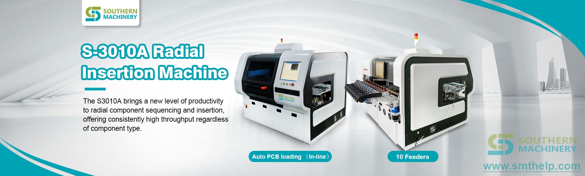
Radial insertion: S-3010B (offline) and the S3000 automatic radial component insertion machine. Odd-form insertion: S-70LD. Terminal, PIN and eyelet insertion: S7020 series, S-7000E and S-7000T. Supporting stations: S-WS450 and S-WS350B wave soldering, SME-6200/S1688 cleaning, SLD250/SUL250 magazine handling, plus AOI, SPI and X-ray inspection.
Talk to Southern Machinery about your insertion cell
If you are specifying a THT or mixed-technology insertion line — or trying to stabilise one you already run — send us your PCB sizes, component list and target takt, and we will map the preparation routine and tooling to your product mix.
- Email: jasonwu@smthelp.com
- Phone / WhatsApp: +86 13602562576
- Machine catalog and datasheets: https://file.autoinsertion.com
- Machine photos and albums: https://ph.smthelp.com
- Website: https://www.smthelp.com
Southern Machinery — Shenzhen Southern Machinery Sales And Service Co., Ltd. Founded 2011, Shenzhen, China. 237+ customers worldwide. SMT and THT insertion, board handling, wave soldering, cleaning and PCB assembly automation.
Comments