
SM-JWF-01 SMT THT Jumper Wire Feeder by Southern Machinery
The SM-JWF-01 SMT THT Jumper Wire Feeder by Southern Machinery is designed for factories that still rely on operators to cut, form and prepare jumper wires before PCB assembly. It automates jumper wire cutting, forming and feeding for use with SMT mounter platforms, helping EMS, ODM, automotive electronics, medical electronics and industrial control manufacturers reduce repetitive manual handling, stabilize wire preparation quality and integrate jumper wire feeding into a more efficient PCB assembly workflow. Final cycle time, component fit and line ROI should always be confirmed against the wire material, jumper span, mold configuration and target mounter setup.
Jul 23, 2026 · Updated Jul 23, 2026 · Southern Machinery
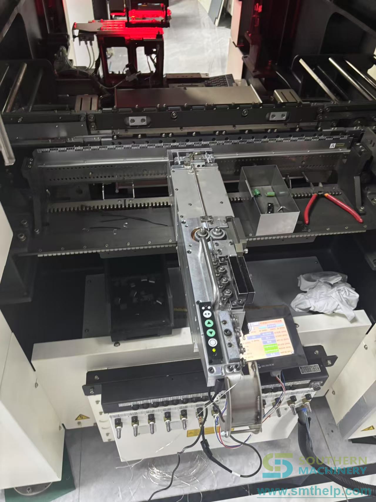
SM-JWF-01 SMT THT Jumper Wire Feeder by Southern Machinery
Jumper wire preparation is a small process step that can create a large production bottleneck when it is handled manually. Operators must cut wire, form the correct span, maintain lead length consistency and feed the material into the next assembly step without mixing or deformation. For EMS, ODM, automotive electronics, medical electronics and industrial control factories, this manual work can slow changeovers and make quality depend too heavily on operator skill.
The SM-JWF-01 SMT THT Jumper Wire Feeder from Southern Machinery is built to automate jumper wire cutting, forming and feeding. The source product document positions it as a compact feeder that can work with any SMT mounter brand and prepare tinned copper jumper wire for PCB assembly use.
Southern Machinery was founded in Shenzhen, China in 2011 and focuses on SMT and THT PCB assembly automation equipment. Across SMT lines, THT insertion, wave soldering, board handling and inspection-related solutions, Southern Machinery supports global manufacturers with high-efficiency, cost-effective equipment, spare parts support and professional training.
What is this machine used for?
The SM-JWF-01 is used to automatically cut, form and feed jumper wires for PCB assembly. In practical production terms, it helps replace repeated manual jumper wire preparation with a controlled feeder process that can be integrated beside an SMT mounter or into a broader PCB assembly workflow.
This is most relevant when a factory uses jumper wires as through-hole conductive links, board-level modifications or electrical interconnects that require consistent wire diameter, jumper span and lead length. Instead of relying on manual cutting and forming, the feeder prepares jumper wires according to the configured mold and process setup.
Core Production Value
Reduce repetitive manual handling
The product document lists automated jumper wire cutting, forming and feeding as the feeder's main function. This matters because manual jumper preparation is repetitive, easy to interrupt and difficult to scale when production mix changes. Automation gives process engineers a more stable method for feeding prepared jumper wires into assembly.
Stabilize jumper wire quality
Consistent jumper span and lead length are important for insertion fit and downstream process stability. The source document specifies a jumper span range of 6 mm to 40 mm, customizable by mold change, and a lead length range of 3 mm to 5 mm. These values should be confirmed against the final PCB design, wire material and insertion method before production release.
Fit existing SMT mounter environments
The source document describes the feeder as universal for any SMT mounter brand. For buyer evaluation, this means the key engineering work is not only the feeder itself, but also the mechanical and process interface to the selected mounter, placement program and board flow.

Typical Applications
The SM-JWF-01 is suitable for PCB assembly environments where jumper wires are still prepared manually or semi-manually. Typical use cases include:
- EMS factories producing mixed electronic assemblies with recurring jumper wire requirements.
- ODM production teams that need more consistent preparation for jumper wire variants.
- Automotive electronics lines where repeatability and process control matter more than manual flexibility.
- Medical electronics and industrial control PCB production where wire preparation quality must be stable across shifts.
- SMT or THT process improvement projects focused on reducing operator-dependent preparation work.
The feeder should be evaluated with the actual wire diameter, jumper span, board design and mounter interface before final specification.
How to Connect It Into a Complete PCB Assembly Line
In a complete PCB assembly setup, the jumper wire feeder should be treated as a controlled material preparation and feeding module, not as an isolated accessory. A practical integration flow can look like this:
- Confirm the jumper wire requirement from the PCB design, including wire diameter, span and lead length.
- Match the mold configuration to the required jumper span. The source document notes approximate 5-minute mold replacement, but real changeover time depends on operator training and production procedure.
- Position the feeder according to the SMT mounter or assembly process interface.
- Validate formed jumper geometry on sample boards before releasing mass production.
- Connect the output to the broader line plan, including upstream SMT placement, THT insertion where applicable, wave soldering or selective soldering, board handling and inspection.
Southern Machinery can support full-line discussions covering SMT, THT automation, wave soldering, board handling and inspection options, so the feeder can be reviewed as part of the complete PCB assembly process rather than as a standalone purchase.

Key Selection Parameters for Buyers
Before specifying a jumper wire feeder, manufacturing engineering and purchasing teams should confirm the following parameters:
| Selection item | Source document value or evaluation point |
| --- | --- |
| Model | SM-JWF-01 |
| Function | Automated jumper wire cutting, forming and feeding |
| Compatibility | Universal for any SMT mounter brand, subject to final integration confirmation |
| Speed | Up to <=1.5 seconds per piece, depending on configuration and process validation |
| Wire diameter | Phi 0.5 mm to 1.2 mm tinned copper wire |
| Jumper span | 6 mm to 40 mm, customizable by mold change |
| Lead length | 3 mm to 5 mm |
| Control system | Single-chip microcomputer program control |
| Power supply | 24V DC / 50HZ, 150W |
| Dimensions | 580 mm x 50 mm x 180 mm |
| Maintenance | Easy operation and approximately 5-minute mold replacement, depending on setup and training |
These values come from the selected local product document and should be treated as pre-sales engineering data. Final acceptance should be based on sample wire testing and mounter integration checks.
ROI, Quality and Capacity Impact
The strongest ROI case for the SM-JWF-01 is not a single guaranteed payback number. It comes from reducing repeated manual wire preparation, lowering handling variation and making jumper wire feeding easier to schedule within a complete PCB assembly process.
For production managers, the value areas are:
- Labor reduction: fewer operator minutes spent cutting and forming jumper wires by hand.
- Quality stability: more consistent jumper wire geometry when the mold and wire material are correctly matched.
- Line balance: faster and more predictable preparation for boards that require jumper wires.
- Changeover control: mold-based span change helps standardize setup when multiple jumper sizes are used.
- Integration flexibility: the feeder is described as compatible with SMT mounter brands, subject to final mechanical and process confirmation.
Any ROI estimate should be calculated from the factory's own labor cost, current manual cycle time, defect/rework data, jumper wire volume and number of product changeovers.
FAQ
Can the SM-JWF-01 work with my SMT mounter?
The source document describes the feeder as universal for any SMT mounter brand. Final compatibility should still be confirmed with the exact mounter model, feeder interface, available space and production process.
What wire material does it support?
The listed wire range is Phi 0.5 mm to 1.2 mm tinned copper wire. Other wire materials or unusual wire conditions should be tested before production approval.
What jumper span can it form?
The listed jumper span is 6 mm to 40 mm, customizable by mold change. The correct span should be matched to the PCB design and validated with sample boards.
How fast is the feeder?
The source document lists speed as up to <=1.5 seconds per piece. Actual output depends on wire condition, mold setup, mounter integration and line balancing.
Is this only for high-volume factories?
No. It is also relevant for high-mix factories where operators repeatedly prepare jumper wires and where consistent setup control is important. The business case should be calculated from actual jumper wire volume and labor requirements.
Can Southern Machinery help with full-line planning?
Yes. Southern Machinery focuses on SMT and THT PCB assembly automation equipment and can discuss SMT, THT insertion, wave soldering, board handling, inspection, spare parts support and professional training as part of a complete line solution.
CTA: Validate Your Jumper Wire Process
If your PCB assembly team is still preparing jumper wires manually, send Southern Machinery your jumper wire diameter, required span range, lead length target, PCB application and SMT mounter model. The team can help review whether the SM-JWF-01 SMT THT Jumper Wire Feeder is a fit for your line and what technical confirmation is needed before mass production.
Comments