
SAF1001 Axial Tape Feeder for Smart EMS PCB Assembly
The SAF1001 is a horizontal axial tape feeder that feeds taped resistors, triodes and jumper wires to an axial insertion head at 0.8 seconds per feed and ±0.3 mm accuracy, for 3 x 3 mm to 6 x 20 mm parts on 35 / 64 / 92 mm paper tape. It replaces the bench where operators hand-pick axial components and presents parts at the inserter's own cycle, cutting the manual seconds that never appear on a capacity sheet. Published data covers a 1000-feed test and a 48-hour aging test, 24 V DC and 0.4-0.6 MPa air, an 8-core IO plug, and an included installation and training service. Choose it for datum-specific mounts, or its sister ATF-1002 for JUKI, Panasonic, Yamaha, FUJI and UIC platforms.
Oct 6, 2026 · Updated Oct 6, 2026 · Southern Machinery
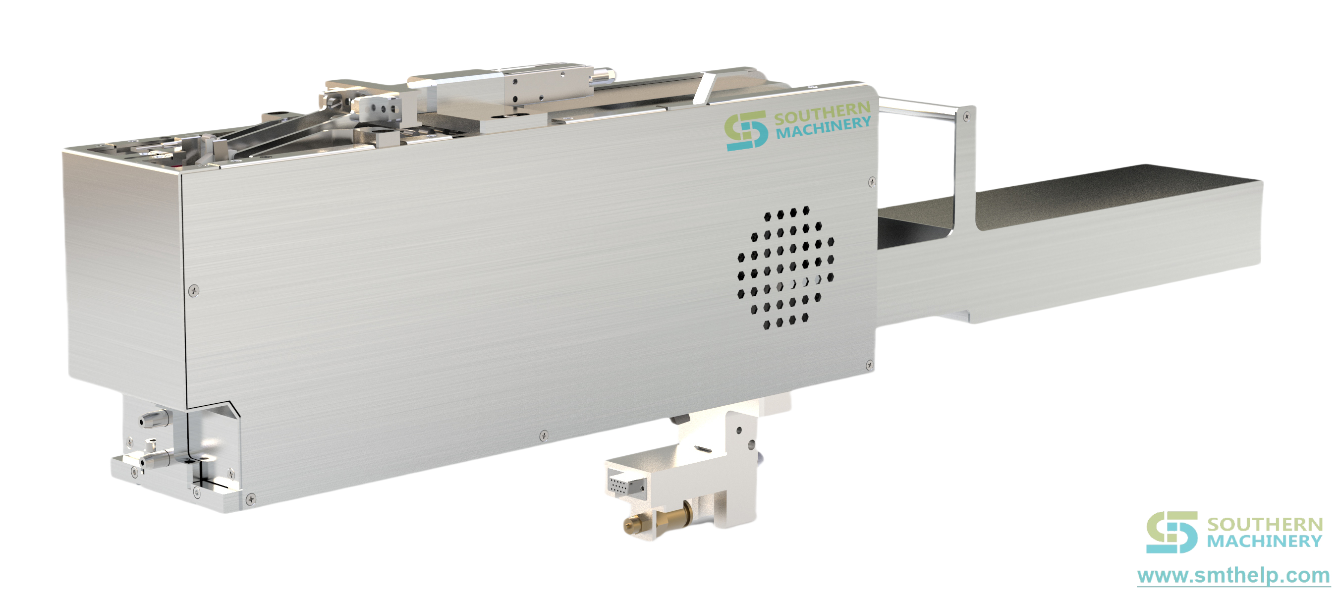
The SAF1001 is a horizontal axial tape feeder that presents taped resistors, taped triodes and taped jumper wires to an axial insertion head at 0.8 seconds per feed and ±0.3 mm accuracy. It takes components from 3 × 3 mm to 6 × 20 mm on 35 / 64 / 92 mm paper tape and locks onto the machine datum with a positioning key and press block.
Why do taped axial parts still decide your real output?
On a mixed-technology EMS floor the bottleneck is rarely where the capacity spreadsheet says. The axial inserter is a machine; beside it sits a bench where taped axial parts are opened by hand, all shift — and nobody logs it. The inserter was never the constraint; the bench was.
Hand-picking costs seconds the inserter could be placing. Taped axial parts arrive in packaging designed for protection, not automation, so they are absorbed the expensive way, without anyone logging the rate.
Manual feeding escapes errors. A person loading axial components can invert polarity, mix adjacent values or fatigue by hour six, while the feeder presents one part at a time at a known pitch.
Changeovers burn uptime. Without a dedicated tape path, every added part number means another reel and another stop; three standard tape widths let one feeder carry the axial family.
What does 0.8 seconds per feed mean on a real line?
Throughput on an axial insertion cell is set by the insertion head's pick cycle, not by the feeder. At 0.8 s per feed with air-pressure speed regulation, the tape path presents the next component faster than the head takes the previous one, so the cell runs at the inserter's cycle time and the hand-picking seconds leave the cycle.
The ±0.3 mm accuracy at the pick position keeps pick height and offset stable from cycle one to cycle fifty thousand: the tape is defined at three points, the fibre reads the index, and an air cylinder fine-tunes when the index alone is not enough.
SAF1001 published specifications, exactly as written
Quoted from the SAF1001 product document and the horizontal taped-feeder operation manual (design version 20211210A02).
- Model and function — SAF1001 axial tape feeder; automatic horizontal tape feeding of axial components to the insertion head
- Applicable materials — taped resistors, taped triodes, taped jump wires
- Component size range — 3 × 3 mm up to 6 × 20 mm
- Tape width — 35 mm, 64 mm, 92 mm (customised by width); paper thickness greater than 0.2 mm
- Feeding and fixing — horizontal taping tray, materials in boxes, air cylinder forward-pushing, optical fibre sensing plus air-cylinder fine-tuning; positioning key plus press block, custom structures supported
- Waste tape recycling — front-end vertical dropping; reflow-type take-up optional
- Speed and accuracy — 0.8 s per feed; ±0.3 mm
- Voltage, current, air — 24 V DC, 1 A average / 3 A peak; 0.4 – 0.6 MPa dry clean air
- Size, weight, interface — 730 × 95 × 212 mm, 8 kg; 8-core φ16 mm aviation plug, IO or standalone operation
- Reliability recorded — 1000-consecutive-feed test and a 48-hour aging test with no abnormalities
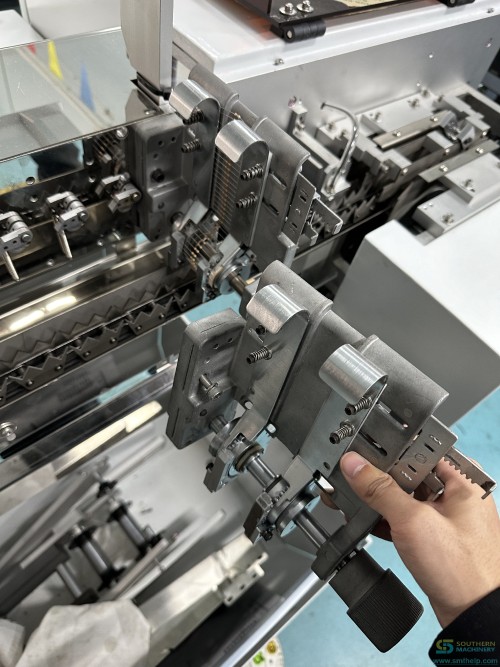
How does the SAF1001 feed one component? Five documented moves
1 — Load the tray
The taped reel drops into the horizontal tray, the path runs flat, the leader passes the optical fibre head, and the waste-tape outlet stays clear.
2 — Lock onto the datum
A positioning key plus a press block, in the manual's own words: seat the feeder against the datum and close the clamp. A loose mount is the manual's most common cause of pitch drift.
3 — Sense the index, tune with air
The fibre reads the tape index and an air cylinder nudges position, closing the accuracy loop at ±0.3 mm. Clean the fibre head weekly with alcohol.
4 — Advance and trim, on four delays
The feed cylinder pushes the tape and the cut cylinder trims the lead, each independently speed-adjustable. Four delays are set per part number: material-arrival, feed retract, cut extend and cut retract.
5 — Pick, then drop the waste tape
The head takes the leading component, with a lifting-height screw setting how far the part rises into the pick zone; the paper strip then drops out of the front-end outlet.
The 8-core φ16 mm aviation plug carries 24 V, 0 V and the IO handshake: start X6 from the host, ready Y3 back, and clamped X7 to release the cut knife, all 0 V active. Manual mode steps the two cylinders for setup and jam clearing.
SAF1001 or ATF-1002: which axial tape feeder fits your machine?
The two models are sisters in the same horizontal-tape family, and the difference that matters at quotation time is the machine interface.
Choose the SAF1001 when tape width and tray geometry are the variable and the host machine needs a datum-specific mount: as published it uses the positioning key plus press-block fixing method and supports non-standard equipment through a custom interface.
Choose the ATF-1002 when the host machine is a JUKI, Panasonic, Yamaha, FUJI or UIC platform, where the family already documents the interface.
For formed leads rather than a straight axial lead, the family also documents a horizontal K-forming variant with a forming cylinder and press-leg block (manual design version 20250306A03). Send the machine make and model plus a sample taped reel, and Southern Machinery quotes the interface variant rather than a generic feeder.
How does the feeder integrate into a full PCB assembly line?
A feeder is a subsystem, not a line: in a THT insertion cell it sits on the axial inserter, and the cell finishes through wave or selective soldering, lead trimming and inspection. Three fits decide whether it works — part fit (3 × 3 mm to 6 × 20 mm on 35 / 64 / 92 mm tape, custom widths via the five-day design service), machine fit (positioning key plus press block, custom structures supported, sister interfaces on JUKI, Panasonic, Yamaha, FUJI and UIC platforms) and supply fit (24 V DC at 1 A average / 3 A peak and 0.4 – 0.6 MPa dry clean air through one aviation plug and one air line).
Southern Machinery publishes the surrounding stages: the route from bare board to finished assembly on the PCB assembly line overview, the feeder family on the SMT and THT feeder category and the THT feeder category, the insertion machines on the THT machine category, and the integration offer in the one-stop PCB assembly total solutions page. Catalogues are indexed in the file library.
What is the payback on an axial tape feeder?
The product document supplies a method, not a quotation:
Payback (years) = feeder price ÷ annual freed hand-picking labour
Annual freed labour = components hand-picked per board × boards per day × manual pick-and-place seconds per component × share the feeder takes over × working days per year ÷ 3600 × loaded wage per hour.
Example arithmetic, for illustration only and depending on configuration, subject to final technical confirmation: 6 taped axial components per board, 400 boards per day, 8 seconds of manual pick-and-place per component, 80% taken over, 250 working days, US$12 per hour. That frees roughly 4.3 operator-hours per day, about US$12,800 per year; against an illustrative feeder price of US$3,000, payback lands near three months. Substitute your own quotation for the price. The formula ignores the escapes a manual bench lets through and the machine slot the feeder frees up, so treat the result as a floor, not a forecast.
What the source does not publish
Not specified in source — contact Southern Machinery to confirm: feeder price, the host machine's maximum board size envelope, field defect or PPM statistics, and any guaranteed line output figure. Published lead times cover hardware: a 1-day spare-parts commitment and a 5-day customised design service.
FAQ
What components can the SAF1001 feed?
Taped axial parts from 3 × 3 mm to 6 × 20 mm on 35 / 64 / 92 mm paper tape thicker than 0.2 mm: resistors, triodes and jump wires. Custom widths use the documented path.
How fast can it feed, and what throughput should I plan?
0.8 s per feed with air-pressure speed regulation, at ±0.3 mm accuracy. Plan throughput from the insertion head's pick cycle, not the feeder. The document also records a 1000-consecutive-feed test and a 48-hour aging test with no abnormalities.
What are the power and utility requirements?
24 V DC at 1 A average and 3 A peak, plus 0.4 – 0.6 MPa dry clean air, through the 8-core φ16 mm aviation plug and the standard air inlet. The manual warns never to short 24 V to 0 V, and that insufficient inlet pressure stops parts advancing fully.
What happens when a component jams, and what comes with the feeder?
Most jams are tuning, not hardware: low air pressure that stalls parts, a dirty fibre head, or a wrong feed-claw stop position. Free installation and training are included — guided mounting, tape threading and the four-delay tune — and numbered wear parts carry a 1-day lead-time commitment.
Get a feeding evaluation for your taped axial parts
Southern Machinery has built SMT and THT PCB assembly equipment from Shenzhen since 2011, with a feeder family covering axial, radial, tube, bowl, belt, label and tray feeding. Send a photo of the taped component with your board volumes and the host machine model, and you will get back a feeding evaluation with the tray configuration and tuning procedure. Start from the Southern Machinery feeder category or the SMT machine category.
Comments