
S580 Series Strain Gauge & PCB Strain Measurement Device
Southern Machinery S580 strain gauge and SDL series PCB strain measurement device quantify board stress to prevent solder joint cracks in SMT assembly.
Aug 7, 2026 · Updated Aug 7, 2026 · Southern Machinery
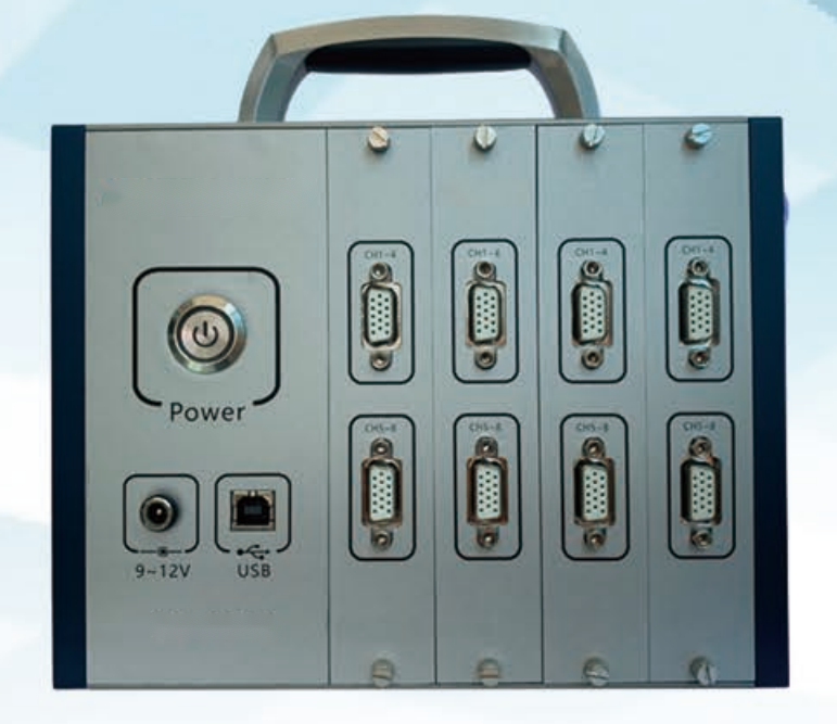
S580 Series Strain Gauge & PCB Strain Measurement for Reliable SMT Assembly
Mechanical stress is one of the most overlooked causes of field failures in assembled PCBs. Cracks in BGA and chip component solder joints rarely start at reflow — they start when a board is flexed during depaneling, wave soldering, connector insertion, or handling. Southern Machinery's S580 series strain gauge and SDL series PCB strain measurement device give EMS and OEM engineering teams a practical way to measure that stress and prevent it from becoming a warranty claim.
What is this machine used for?
The S580 series strain gauge, paired with the SDL series measurement device, is used to quantify mechanical strain on printed circuit boards. The SDL series uses a network of miniaturized strain gauges and sensors embedded directly into the PCB, with Wheatstone bridge circuits printed onto the board. When the board bends, twists, or stretches, the strain gauges convert that mechanical deformation into a change of electrical resistance. The result is real-time strain mapping across the board, transmitted wirelessly to a connected device for analysis.
In plain terms: instead of guessing whether a board flexes too much during a production step, you measure it. The device closes the loop between PCB design, assembly process settings, and actual mechanical loads — during prototyping, qualification testing, and field use.
Why PCB strain measurement matters
Solder joint cracking from board flex is a documented failure mode. Standards such as IPC/JEDEC-9704 (Printed Circuit Assembly Strain Gage Test Guideline) exist specifically to help manufacturers characterize assembly and test processes that subject boards to mechanical stress. Common sources of damaging strain include:
- Depaneling / PCB separation by router, V-score, or punch
- Wave soldering pallet clamping and board support
- Connector and through-hole component insertion
- Manual handling, stacking, and magazine loading
- ICT / FCT test fixtures and press-fit operations
A strain measurement device lets a process engineer identify which step exceeds acceptable limits, then correct the fixture, support tooling, or process parameters before field failures appear.
Typical Application Scenarios
The SDL series is designed for space-constrained PCBs, making it suitable across industries:
- EMS / contract manufacturing — qualifying new board designs and assembly lines before high-volume ramp
- Automotive electronics — ECU, BMS, and sensor modules where vibration and thermal cycling demand strong solder joints
- Aerospace and defense — high-reliability assemblies where board structural integrity is mission-critical
- Industrial control — PLCs, drives, and instrumentation exposed to mechanical shock in the field
- Consumer electronics — thin, large-format boards that flex easily during handling and assembly
How It Integrates into a Complete PCB Assembly Line
The strain gauge device works as a quality engineering tool alongside production equipment, not as another station in the line. Typical workflow:
- Prototype phase — gauges are integrated into sample boards; the board runs through the actual assembly line (stencil printing, pick-and-place, reflow, wave soldering, depaneling).
- Measurement phase — strain data is collected wirelessly at each mechanical step — clamping, conveying, cutting, insertion, test.
- Analysis phase — engineers review strain maps, compare against IPC/JEDEC-9704 limits, and adjust fixtures or process parameters.
- Qualification phase — the validated process becomes the standard for that product family, and the device can be re-used on new designs.
Because the sensors are printed directly onto the PCB, no external sensor rig occupies line space, and the board's functionality is not affected.
Key Selection Parameters
When evaluating a PCB strain measurement solution, confirm these points with the supplier:
- Gauge type and mounting method — printed / embedded vs. bonded strain gauges, and compatibility with your board material and finish
- Measurement range — whether the system can capture extreme stress events, not just steady-state load
- Data transmission and software — wireless transmission, sampling rate, and analysis interface for strain mapping
- Board size and layout constraints — minimum sensor footprint and integration effort on dense PCBs
- Standard compliance — how the data maps to IPC/JEDEC-9704 strain limits and reporting requirements
- Process coverage — which assembly steps (depaneling, wave soldering, insertion, test) you need to characterize
ROI, Quality & Throughput Perspective
The business case for strain measurement is straightforward:
- Fewer field failures — identifying flex-induced cracks during qualification instead of after shipment
- Faster new-product introduction — quantitative data replaces trial-and-error fixture tuning
- Lower rework cost — catching stress issues at the process level rather than at final test or in warranty
- Defensible process documentation — strain reports support customer quality audits and automotive/medical PPAP-style submissions
- Reusable investment — one measurement device serves many product lines over multiple years
For Southern Machinery, this is part of a broader commitment: SMT/THT PCB assembly automation equipment, full-line solutions from SMT placement to wave soldering, board handling, and inspection, backed by global support, spare parts, and training.
FAQ
Q: What does a PCB strain gauge measure?
A: It measures mechanical deformation of the board — bending, torsion, and tension — by converting strain into a change in electrical resistance, giving real-time quantitative stress data.
Q: Why is PCB strain testing needed in SMT assembly?
A: Board flex during depaneling, soldering, insertion, and handling can crack BGA and chip solder joints. Strain testing (per guidelines like IPC/JEDEC-9704) identifies which process step exceeds safe limits.
Q: Does the strain gauge device work with existing SMT lines?
A: Yes. The sensors are embedded in sample PCBs, which then run through your normal assembly line. No line reconfiguration is required — data is collected wirelessly during the process.
Q: Can it be used on production boards as well as prototypes?
A: The SDL series supports prototyping, qualification testing, and field-use monitoring, giving visibility across the whole product lifecycle.
Q: Which industries benefit most from PCB strain measurement?
A: Automotive electronics, aerospace, industrial control, EMS, and consumer electronics — anywhere board flex threatens solder joint reliability.
Q: How do I get started with a strain measurement setup?
A: Contact Southern Machinery with your board size, assembly process steps, and reliability requirements. The team can advise on gauge integration and measurement workflow for your line.
Contact Southern Machinery for Configuration Advice
Southern Machinery, founded in 2011 in Shenzhen, China, has served 237+ customers worldwide with SMT/THT PCB assembly automation equipment — from insertion machines and wave soldering to board handling, cleaning, and inspection. For configuration advice on the S580 series strain gauge and SDL series PCB strain measurement device, contact Jason Wu at jasonwu@smthelp.com.
- Browse machine catalogs: file.autoinsertion.com
- See machine photos: ph.smthelp.com
- Website: www.smthelp.com
Video: S580 series strain gauge applied — watch on YouTube
Comments