
Odd-Form Insertion Machine Components by Southern Machinery
Which THT parts an odd-form insertion machine can place, how packaging sets the feeder, and the published numbers to confirm before you order.
Oct 7, 2026 · Updated Oct 7, 2026 · Southern Machinery

Direct answer. An odd-form insertion machine places the through-hole components no placement
machine will accept — tact switches, strip connectors, copper inserts, horizontal braided parts,
PINs, eyelets, relays and transformers. Southern Machinery's 2024 platform manual publishes a
theoretical speed per component class: 0.6 seconds per point for tact switches, 0.55 for
connectors and copper inserts, 1 second for horizontal braided parts. The machine reads the hole
positions, corrects the deviation, inserts and clinches.
What is an odd-form insertion machine used for?
It automates the last manual bench on a through-hole line: the parts left after radial and axial
insertion. Our own documents define an odd-form component as an odd-shaped through-hole part that
cannot be placed automatically by a standard through-hole insertion machine because of its height,
shape or weight — which covers transformers, relays, connectors, crystals, inductors and switches.
Why hand insertion is a quality problem, not just a labour cost
The 2024 manual lists bent feet as a named fault with three causes: inaccurate insertion, heads out
of centre, and the wrong gap between the insertion head and the board — all mechanical settings,
and none can be held by eye at 0.05 mm. Automatic correction accuracy is stated at 0.015 mm,
point-to-point positioning at 0.025 mm and repeat positioning at 0.05 mm.
Which THT parts can an odd-form insertion machine insert?
Two documents answer this: the platform specification table, measured on four object classes, and
the product documents that extend it.
- Tact switch class — 0.6 seconds per point, bulk, bowl and track; switch bodies 6.0 × 6.0 mm
to 10 × 10 mm, handle length up to 3.5 mm.
- Connector and copper insert classes — strip headers and iron-sheet inserts, 0.55 seconds per
point, bulk packaging.
- Horizontal braided class — 1 second per point, 52 mm tape.
- PIN — 1.2 to 4.0 mm round and tape pin, up to three heads in one pass.
- Eyelet — eyelet or custom PIN, vibratory bowl feed.
- Odd-form parts — 3 × 3 mm to 30 × 30 mm, clinching angle 15 to 30 degrees on four heads,
lead diameter below 1.0 mm with at least 2 mm of exposed lead (S7900 catalogue).
Board size eliminates models faster than any component detail, and the variant documents quote
windows from 50 × 50 to 480 × 390 mm. Measure your largest and smallest board first.
The packaging decides the feeder — and the feeder decides the machine
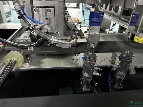
The feeder is not an accessory here, it is the product. Six families are documented, each with its
own rate, load limit and component list:
- Vibratory bowl with track — bulk tact switches, connectors, copper inserts, crystals, ICs.
- Standard tape feeder — axial leaded tape, pitch to 22.5 mm, 90 degree bent lead function,
1.1 to 1.5 seconds per piece.
- Tube feeder — relays and transformers in tubes, 0.8 to 1.5 seconds per piece, tubes to
50 × 50 × 50 mm, load to 4 kg.
- Customised tray feeder — parts that cannot be fed from bulk or tape, 0.5 to 0.8 MPa, 2000 W.
- Radial tape feeder — radial taped parts, plus a 90 degree bend variant.
- Label and belt feeders — taped labels, and loose parts that do not orient in a bowl.
Build your own component-to-feeder table
List every odd-form part on your highest-volume board with three fields beside it: packaging, size,
quantity per board. Packaging selects the feeder, size checks the board window, quantity decides
the head count. The manual's fault table is dominated by feeding — blocking and irregular feeding
is the one symptom group with four named causes — so ask how long a changeover takes and who does it.
Which published numbers should you plan against?
Plan against the configuration, not the brochure. The 2024 manual gives these values:
- PCB handling — 80 × 80 to 380 × 250 mm, automatic worktable width adjustment, 3 second
installation time.
- Control — Windows on an industrial PC, 17 inch colour LCD, online visual programming,
Excel-format programs, RS-232C, PCB QR code scanning, insertion force detection (optional).
- Utilities — AC220V single phase, 1.6 kVA with a 2.0 kW maximum; air 5 to 6 kgf/cm² at about
0.6 m³/min; noise 70 dB.
- Footprint and mass — 1995 × 1250 × 1530 mm, 1500 kg for the configuration described.
Where our own documents disagree, and how to read it
Nine documents sit behind this series and on ten items they differ: dimension appears as four
values, machine weight as three, power as three, air pressure as three, and throughput as a range
spanning a factor of three. Sort every figure into three buckets — firm (stated for your model
or on your drawing), range (plan for the worst case: size for the highest kVA quoted, supply
0.6 MPa air and regulate at the machine) and open (nobody stated it, which is not zero). The
spread is configuration: four naming families describe overlapping machines — S7020T, S7020E,
S7020P, S7020S and S7020F at 12,000 and 5,000 CPH, S-7000P, S-7000E and S-7000D at 8,000 and 4,000
CPH, and the four-head OIM-2FS-W at 4,000 CPH. The clinch is the same kind of decision: four forms
are documented (outward, inward, circular, two-turn bend, plus an N form on the terminal variant)
and the right one comes from a pull test on a sample.
How does an odd-form inserter connect to a complete PCB assembly line?
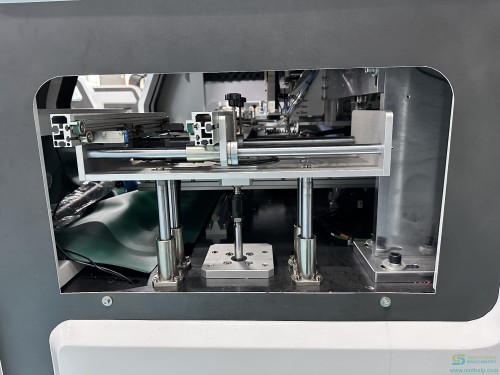
The documented sequence is: the loader transfers the PCB to the left track; the track carries it
onto the X-Y worktable, located by a stop plate and pressing cylinder; the camera corrects the hole
deviation; the head inserts and the detection system verifies; the clinch fixes the lead; the right
track hands the board to the unloader. SMEMA connectors, automatic load and unload, and
left-to-right or right-to-left transfer are documented, and the family runs beside axial and radial
inserters. Our
odd-form insertion machines cover that
stage, the S7000 platform page
carries the detail, the DIP assembly line
shows the sequencing, and
board handling covers the flow.
What does it cost to run an automated odd-form line?
Cost released labour first, using your own inputs and the published per-point speed for your
component class:
Annual labour addressed = odd-form components per board × boards per year
                        × seconds of manual insertion per component
                        × share the machine takes over ÷ 3600
                        × loaded wage per hour

Simple payback (months) = machine investment ÷ (annual labour addressed ÷ 12)
**Worked example — illustrative only, depends on configuration, subject to final technical
confirmation.** At 60 odd-form components per board, 8,000 boards a year, 12 seconds of hand
insertion per component, 90 percent taken over by the machine and a loaded wage of USD 15 an hour,
hand work replaced is 60 × 8,000 × 12 × 0.9 = 5,184,000 seconds a year — about 1,440
operator-hours, or roughly USD 21,600 a year, so each USD 1,800 of investment is one month of
payback. Replace every input with your own measured value: the manual publishes no price and no
savings claim.
Two things belong in the same model. Insertion force detection stops a cycle before an over-force
insertion deforms the part or the board, and stress can be measured rather than assumed — our own
stress test document works to IPC-9704 and treats plus or minus 500 microstrain as qualified. The
service terms are published too: 7x24 worldwide support, free installation and training, a one-day
lead time on spares and a one-month customisation window. Two source documents quote monthly
maintenance in two different currencies, so ask for a priced wear-part list instead.
FAQ
Which THT parts can the S7000 series insert?
Four object classes in the 2024 manual — tact switch, connector (strip header), copper insert (iron
sheet) and horizontal braided — extended to PIN from 1.2 to 4.0 mm, eyelet, tact switches from
6.0 × 6.0 to 10 × 10 mm, and odd-form parts from 3 × 3 to 30 × 30 mm.
Is the real throughput 4,000, 8,000 or 12,000 components per hour?
All three appear in our own documents and none is wrong, because they do not measure the same
thing. The manual gives 0.55 to 1 second per point per head; the S7020 series document quotes
12,000 CPH for the two-head variants and 5,000 CPH for the odd-form variant; S-7000P and S-7000D
quote 8,000 CPH; S-7000E and OIM-2FS-W quote 4,000 CPH. Ask for the class, head count and feed
method beside any number.
Do we need insertion force detection?
It is listed as optional, and we recommend specifying it: it stops the machine when insertion force
exceeds the limit, so an over-force cycle never completes. For an evaluation, send a populated
board close to production condition plus a sample of each odd-form component in its real packaging.
Can it run in line with our existing THT equipment?
SMEMA connectors, automatic PCB load and unload, and left-to-right or right-to-left transfer are
documented, with RS-232C as the stated interface. Your conveyor interfaces, board flow direction
and rail heights decide it.
Next step: send us a board and a bag of parts
Write down every odd-form part on your highest-volume board — packaging, size, quantity — and send
that list with a populated board and a sample of each part. Southern Machinery will confirm the
feeder for each packaging type, the head count your mix needs, the clinch form to pull-test and a
throughput figure built from published per-point speeds.
Founded in Shenzhen, China in 2011, Southern Machinery serves 237+ customers worldwide with SMT/THT
PCB assembly automation — placement, insertion, wave and selective soldering, board handling and
inspection — backed by global service, spare parts and training. The figures are in
the S7000 platform manual 2024
and the S7900 feeder catalogue 2025.
Email info@smthelp.com with your component list and we will map it to a configuration.
Comments