
Nozzle Data and Settings on an Odd Form Insertion Machine | Southern Machinery
Nozzle data is the part of an odd form insertion machine program that decides whether a component is actually picked reliably — tool type, tip geometry, vacuum, pick-up height and tool-centre offset. Lesson 2 of Southern Machinery's odd form machine training series covers nozzle data and settings, and this guide explains what buyers should verify: tooling per part family, custom grippers and nozzles for unusual parts, spare-tool policy, and how tooling errors surface as bent leads and missed picks at wave soldering.
Sep 20, 2026 · Updated Sep 20, 2026 · Southern Machinery
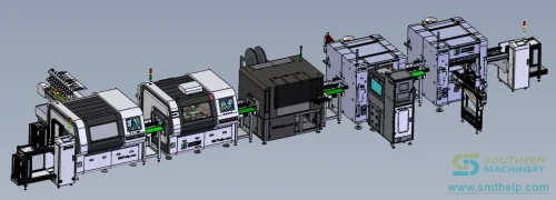
Nozzle Data and Settings on an Odd Form Insertion Machine | Southern Machinery
On an odd form insertion machine, the nozzle is the only part of the machine that ever touches the component. Every other decision in the program — where the part sits on the board, how deep the leads are pushed, how the leads are clinched underneath — is executed through a tool that is measured in millimetres and worn down by every pick it makes. That is why the second lesson in Southern Machinery's odd form machine training series deals with nozzle data and settings, immediately after the start-process and program-file lesson and before component data, PCB data and mark points.
The distinction matters for buyers. Insertion speed and accuracy are published in a catalogue. Nozzle data is not — it is a per-part configuration that decides whether a light radial capacitor is picked cleanly, whether a heavy transformer is held firmly enough to be seated, and whether a gripper releases a connector without disturbing it. The same machine, with the same mechanics, will run a good shift or a bad one depending on how its tooling is defined.
The training lesson is embedded below.
<iframe width="100%" height="480" src="https://www.youtube-nocookie.com/embed/hgivSvZezqo?rel=0" title="Lesson 2 on Odd Form Machine - Nozzle Data and Settings" frameborder="0" allow="accelerometer; autoplay; clipboard-write; encrypted-media; gyroscope; picture-in-picture; web-share" referrerpolicy="strict-origin-when-cross-origin" allowfullscreen></iframe>
Direct link: watch Lesson 2 of the odd form machine training series on YouTube
What is this machine used for?
An odd form insertion machine is the THT station that handles what the rest of the assembly line cannot. Transformers, relays, connectors, fuse holders, terminal blocks, radial electrolytic capacitors, inductors, lamps and optoelectronic parts are neither radial tape, axial tape nor SMD. They arrive in trays, tubes, vibratory bowls or loose bags, with different lead pitches, asymmetric bodies, different weights and no shared presentation standard. A radial inserter cannot be pointed at them, and manual insertion gives you one operator, one part, one board at a time.
An odd-form machine picks each part with a nozzle or a gripper, presents it to the board, seats the leads into the programmed holes to a programmed depth, and clinches underneath so the board can continue into wave soldering without being re-handled.
None of that happens without tooling. A radial tape part is presented in a fixed orientation through a fixed feeder — the machine knows where the body is because the tape says so. An odd-form part is not. It has to be grasped — from a tray pocket, a tube, a bowl track or a belt — and the accuracy of that grasp is set entirely by nozzle data and nozzle settings. Lesson 2 is the lesson that makes the rest of the program physically possible.
As a reference point for the equipment class, the documented specification of the S-70LD odd form insertion machine describes four insertion heads with four adjustable feeders (tape or vibration plate), a 4,000 CPH insertion speed (3,800 CPH noted for radial resistor insertion), ±0.05 mm insertion accuracy, components from 3×3 mm to 30×30 mm and up to 50 mm high, PCBs from 50×50 mm to 300×300 mm at 0.8–5.0 mm thickness, a 220 V AC / 0.8 kVA supply, air at 0.4–0.6 MPa, noise at or below 75 dB, a machine weight of roughly 1,000 kg, and an industrial computer with vision guidance that recognises lead geometry. Southern Machinery's odd-form platforms, including the S7900 series, address the same class of work at other board sizes and throughput levels.
Note what that table does not contain: a nozzle list. Nozzles and grippers are matched to your part mix, not to a specification sheet, and that is the whole reason this lesson exists.
What "nozzle data" actually controls
Nozzle data is the machine's stored definition of the tool that picks a part — and, in the same record, the parameters that govern how that tool behaves. On the odd-form platform covered by this training series it sits between three other data layers: component data (Lesson 3) defines the part, pickup position setting (Lesson 6) defines where the part is grasped, and nozzle data defines what grasps it and how.
The parameters buyers should expect to find in a nozzle or tool record:
- Tool type per part family. Vacuum nozzle, mechanical gripper, or a custom geometry machined for a specific component. Relays and connectors with asymmetric bodies are frequently gripper work; radial capacitors, lamps and small transformers are usually vacuum work. The record has to say which, and the machine has to know it before it indexes to the feeder.
- Tip geometry and opening. Tip shape, opening size and material. Too small an opening and the part is not held reliably; too large and the nozzle fouls the body or the neighbouring component. This is where custom tooling normally begins.
- Vacuum and blow-off parameters. Pick-up vacuum level and blow-off behaviour, which decide whether a part is held during a fast Z-axis move and whether it is released cleanly into the hole instead of being dragged out of position.
- Z-axis pick-up height and tolerance. How far the tool descends onto the part in the feeder. Too high and the part is not sealed or grasped; too low and the tool crushes the body or the feeder pocket. This is one of the settings most often left wrong when a feeder presentation changes.
- Tool offset / nozzle centre calibration. The stored relationship between the tool tip's true position and the head's programmed coordinates. If this offset drifts, the whole program is displaced by the same amount — the machine still inserts, but insertion accuracy against the PCB data degrades.
- Assignment to components and features. Which nozzle or gripper each component record points at, and which head or tool station holds it. Changing a tool without updating the assignment produces a machine that appears to run correctly and places the wrong component.
- Wear, cleanliness and spare-tool policy. How tool condition is checked, how often tools are cleaned, and whether the tool store is managed as a consumable with defined spares — see the nozzle service section below.
- Storage and identification. Where spare tools live, and how a tool is identified so that the record and the physical tool cannot drift apart.
Screen labels, teach sequences and file structures differ between machine platforms, controller generations and software revisions. Southern Machinery's training content reflects the naming used on the platform being demonstrated, not a universal standard — which is why the honest answer to "how is nozzle data configured?" is always platform-specific, and why the useful buying question is not "does your machine support multiple nozzles?" but "show me tooling for my component mix being set up, assigned and verified on the machine you are quoting."
Why nozzle settings decide pick-up reliability
Two plants can run the same machine and get different output purely from tooling configuration:
- Pick-up failure is the most common cause of an unexplained stop. A missed pick is not a subtle defect — it is a head that arrives at the board holding nothing, or holding a part by one edge. The machine may detect it, may not. Either way it is a cycle lost on the line, and the cause is almost always tool data: wrong tool for the package, wrong pick-up height, degraded vacuum, or a contaminated tip.
- Tool wear is gradual and invisible. Tooling degrades over hundreds of thousands of picks. There is no alarm for a nozzle that has become 5% less reliable — only a rising miss rate that operators compensate for by slowing down or by adding manual checks. A defined tool-inspection and replacement interval is what prevents that drift.
- A part held badly is inserted badly. An off-centre grip carries through the whole cycle: the leads arrive at the hole with a positional error, insertion force rises, leads bend, and seating depth varies board to board. Tooling error becomes a soldering defect several stations later.
- Heavy and light parts need different answers. A heavy transformer needs a tool and vacuum/hold strategy that survives a high-speed move. A light lamp or optoelectronic part needs a tool that will not crush it and a release that will not shift it. One generic tool for everything is the reason some plants conclude odd-form insertion "does not work for our parts".
- Custom tooling is a capability, not a cost. Where a component is unusual, the practical options are: a catalogue tool that is approximately right, a custom tool machined to the part, or manual insertion. The first produces a permanent, low-grade defect rate. Southern Machinery manufactures nozzles and grippers in-house and machines custom geometry to a customer drawing, which is what makes the third option avoidable.
- Tooling policy belongs in the quotation. Ask what the machine ships with, how many tool stations exist, what a spare tool costs, how long a custom tool takes, and who calibrates the tool offset after replacement. Those answers decide your uptime more than the CPH figure does.
Typical applications
1. Home appliance control boards. Air conditioners, washing machines, rice cookers, induction cookers and microwave boards carry relays, connectors and transformers in the same program, often with the same component families repeated across many SKUs. Different body shapes and weights, one machine — tooling data is what lets a single platform handle the whole family without a defect rate that grows with the part variety.
2. Power supply and adapter PCBA. Vehicle power supplies, energy-saving power supplies and ballasts use large, heavy transformers and radial capacitors whose pin patterns leave limited positional tolerance. A tool that holds the transformer off-centre converts a tolerance problem into a bent-lead problem, and the pick-up height that worked for a capacitor is wrong for a transformer.
3. LED drivers and lighting electronics. Long, narrow boards and luminous-character panels push the extremes of the machine envelope and often use optoelectronic parts with defined orientation. Tooling that grips such a part by the body without marking or displacing it is what keeps orientation data meaningful downstream.
4. Automotive and vehicle electronics. Car audio and vehicle power supply boards mix SMT and THT content and carry polarity-sensitive parts. A nozzle that picks a part from the wrong side, or releases it with a shift, turns a polarity control into a polarity defect at the customer.
5. EMS and ODM plants running high-mix DIP assembly. Where one line builds many board variants sharing component families, tooling management is a changeover asset. A tool library that is documented, identified and matched to the component library means a returning product is a program load, a tool check and a first-article run — not a re-teach.
How it fits into a complete PCB assembly line
Tooling is defined at one station, but its consequences travel the whole flow:
- SMT block first. Stencil printing, SPI, pick-and-place and reflow build the SMD side. Southern Machinery's SMT range covers this stage — stencil printers such as the SP-1008 and SP-1200, semi-automatic platforms such as the S-530L for lens and LED component mounting, higher-volume placement on the S-DU800 series, SMT intelligent reel storage for traceable FIFO kitting, and SPI/AOI inspection. Pick-and-place nozzles and odd-form nozzles are the same engineering problem at two different scales, and both are consumables.
- Component preparation. Radial taping, lead forming, bulk capacitor taping with polarity check, axial-to-radial tapping and lead cutting convert loose parts into insertion-ready format. A tool cannot compensate for badly formed leads — the machine will faithfully insert a mis-formed lead, at full speed, to the programmed depth.
- Feeding. Tape, tube, tray, vibratory bowl and belt presentations determine what tool access is even possible, and they set the pick-up height and clearance envelope stored in the tool record. Southern Machinery's feeder range covers these formats, and feeder selection belongs in the same conversation as tooling: a presentation change mid-project invalidates part of the tool configuration.
- THT insertion block. The odd-form inserter works alongside the S-3010B radial inserter, the S-3000 radial insertion machine for DIP assembly, the S4000 axial inserter and the S7020 Series PIN/eyelet/terminal inserter. Each station holds its own tool records, so consistent tool naming and identification across machines is what lets a product move between lines without being set up from zero.
- Soldering and lead finishing. Inserted boards move into lead-free wave soldering — the S-WS450, or the PC-controlled dual-wave S-WS350B — then to the S-320AT inline auto lead cutter, with the S-500G dip soldering machine and the S100B desktop selective soldering machine covering smaller or mixed-technology batches. A tooling error is not contained at the insertion station: it arrives at the wave as a floating-high part or a bent lead, across the whole batch.
- Cleaning and inspection. Stencil and pallet cleaning, SPI, AOI, online wave-solder appearance checking and X-ray equipment catch what insertion produced. The later a tooling defect is discovered, the more of the line it has already travelled through.
- Board handling and support. Magazine loaders and unloaders, conveyors such as the SBF330 wave solder input conveyor, turnover units and buffer storage keep the line flowing while a tool is replaced or a first article is verified. The service ecosystem behind it — spare parts across Panasonic, Fuji, JUKI, Yamaha, Samsung, Siplace, DEK, TDK and Universal platforms, custom nozzles and grippers, feeder calibration, repair, retrofit and operator training — is what keeps the tooling set usable over the machine's working life.
Key selection parameters
The table below lists the parameters worth confirming in a quotation. Where a documented figure exists for the S-70LD platform it is shown as a reference; everything else is a category to verify against your own build.
| Parameter | Documented S-70LD reference | What to confirm for your build |
|---|---|---|
| Tooling concept | Vacuum and gripper tooling with custom geometry available | Which part families will be vacuum-picked and which need a mechanical gripper, measured on your actual parts |
| Nozzle / gripper data | Per-part tool assignment recorded in the controller (covered in this lesson) | How a tool is defined, named, assigned to components and edited |
| Custom tooling | Designed and manufactured in-house to a customer drawing | Availability, lead time and cost per part family, and how one drawing revision is handled |
| Tool offset calibration | Vision-guided platform with lead-geometry recognition | How the tool-centre offset is measured and re-calibrated after a tool change |
| Pick-up height tolerance | Programmable on the platform | Whether pick-up height is stored per component per feeder presentation and how it is verified |
| Vacuum / blow-off | Documented as platform parameters | Air supply quality, filtration and how vacuum degradation is detected |
| Component envelope | 3×3 mm to 30×30 mm, up to 50 mm high | Your largest, heaviest and most fragile odd-form parts, and body-to-body clearance |
| Insertion accuracy | ±0.05 mm | Hole-to-lead clearance and positional tolerance in your board design |
| Insertion heads / feeders | 4 heads, 4 adjustable feeders (tape or vibration plate) | Head count, tool-station count and the feeder mix your part list needs |
| Tool storage & spares | Nozzle service line with stocked spares and lifetime spare-parts guarantee on Southern-supplied equipment | Tool-store capacity, minimum spare set, and the replacement interval your volume implies |
| Speed class | 4,000 CPH (3,800 CPH noted for radial resistors) | Required rate against components per board and changeover frequency |
| PCB range | 50×50 mm to 300×300 mm, 0.8–5.0 mm thick | Smallest board, largest panel and maximum panel weight |
| Line interface | Inline station with SMEMA handshake | Conveyor height, direction and handshake with your existing DIP line |
| Utilities and environment | 220 V AC, 0.8 kVA; air 0.4–0.6 MPa; noise ≤75 dB | Site power, air supply, noise specification and floor loading |
| Footprint / weight | Approximately 1,000 kg | Access for setup, tool changes, maintenance and feeder loading |
Beyond the specification, confirm what you are buying with the machine: a written tooling procedure, an identification scheme that keeps records and physical tools matched, a first-article verification rule that is documented rather than remembered, and a realistic spare-tool set. A quotation without tooling detail is a quotation that will generate its own lead time later.
ROI and quality perspective
From a buyer's perspective, tooling sits exactly where specification turns into production money:
- Tooling cost is small against the cost of the defects it prevents. A nozzle or gripper is a consumable with a defined price. The defects it causes when it is wrong — missed picks, mis-inserted or reverse-inserted parts, bent leads — are paid for at the wave solder, at rework and, worst case, in the field. Southern Machinery's published analysis of the cost asymmetry is blunt: for a transformer with six to ten pins, a single non-seated pin can become a field failure costing many times the board's assembly value, and reworking odd-form defects after wave soldering and cleaning takes roughly 3 to 5 minutes per board with a real risk of damaging adjacent components.
- The manual baseline is the number to beat. Southern Machinery's published analysis of manual odd-form insertion notes that hand-inserted parts take approximately 4 to 10 seconds each depending on operator familiarity, part orientation and presentation, and that across 5,000 boards with four odd-form components per board that variability can add 8 to 16 hours of unplanned labour per shift. That is the labour cost automation removes — but only if the machine can actually pick the part reliably, which is a tooling question before it is a speed question.
- Tool reliability is a throughput lever, not a maintenance detail. Throughput lost to missed picks does not appear in the CPH figure. It appears as lost cycles, retries and operator intervention. Treating tools as managed consumables — with cleaning intervals, replacement intervals and a spare set on the shelf — is usually cheaper than the accumulated cost of running tools until failure.
- Tooling data is a changeover asset. On a high-mix DIP line, a returning order should be a program load plus a tool check. If tool assignments are undocumented and the physical tools are not identified, every repeat order starts with a search, a guess and a first-article re-learn.
- It is a traceability asset. As customers push for documented process control and ESG-style reporting, knowing which tool, program revision and component revision produced a batch is the difference between an answer and a guess — and it decides whether the machine is still supportable years after installation.
Model it with your own numbers: distinct odd-form parts per board, boards per order, pick failure rate per shift, minutes lost per miss, tools consumed per year, and the cost of a defect discovered after soldering. In most plants the arithmetic favours a platform with real tooling data, a managed spare-tool policy and a supplier who can machine a custom tool quickly — long before it favours more manual stations.
Nozzle and gripper support from Southern Machinery
Southern Machinery designs and manufactures SMT nozzles and odd-form grippers in-house in Shenzhen, alongside a multi-brand spare-parts line that includes Panasonic, Fuji, JUKI, Yamaha, Samsung, Siplace/Siemens, DEK, TDK and Universal platforms, plus dedicated auto-insertion spare parts for THT radial and odd-form machines. Where a part is not served by a catalogue tool, the workshop machines custom geometry to the customer's drawing. Feeder calibration jigs with statistical calibration reporting (Cp/Cpk), an in-house repair lab covering lasers, motors, drivers, servo amps and drive mechanisms, and a lifetime spare-parts guarantee on Southern-supplied equipment complete the picture.
FAQ
What is nozzle data on an odd form insertion machine?
Nozzle data is the machine's stored definition of the tool that picks a component: tool type (vacuum nozzle, mechanical gripper or custom geometry), tip shape and opening, vacuum and blow-off parameters, Z-axis pick-up height and tolerance, the tool-centre offset used for placement, and which components that tool is assigned to. It is the tool-side counterpart to component data, which defines the part itself.
How is nozzle data different from component data and PCB data?
PCB data defines the board — dimensions, origin, panel layout and mark points. Component data defines the part — body geometry, lead pitch, height, polarity, depth and clinch. Nozzle data defines the tool that picks and places it. The three are separate lessons in the training series because they are separate controls, and a correct program needs all three to agree.
Why is pick-up height such a critical setting?
Because it is the setting most likely to be wrong when anything upstream changes. Too high and the part is not reliably held or sealed; too low and the tool crushes the body or damages the feeder pocket. Because it is stored per component and per presentation, a feeder change — tape to bowl, tray to tube — usually means pick-up height has to be re-established and re-verified.
Do odd-form machines use vacuum nozzles or mechanical grippers?
Both, and the choice follows the part. Small and regular components are typically vacuum-picked; relays, connectors and asymmetric or heavy bodies are often better served by a mechanical gripper. What matters when evaluating a machine is whether both tool families are supported, how many tool stations exist, and whether custom geometry is available for the parts that fit neither.
Can custom nozzles and grippers be manufactured for unusual components?
Yes. Southern Machinery manufactures nozzles and grippers in-house and machines custom geometry to a customer drawing, which is normally the alternative to accepting an approximate catalogue tool or moving the part back to manual insertion. Buyers should ask for the drawing process, the lead time per part family and how a revision is handled.
What should a buyer ask to see before purchasing an odd-form inserter?
Ask to see tooling set up for your own parts and packaging on the machine being quoted: a tool defined and assigned to components, a pick-up height established and verified, a tool offset calibrated after a change, a custom or unusual part picked reliably, and a documented spare-tool and cleaning policy. A prepared demo with perfect tooling does not answer any of those questions.
Contact Southern Machinery
Southern Machinery (Shenzhen, China; established 2011; 237+ global customers) designs and manufactures SMT, THT and PCB assembly automation — insertion machines, wave soldering, board handling, cleaning, inspection, feeders and nozzles, and the spare parts, training, retrofit and repair services around them.
For help evaluating an odd-form insertion machine, specifying nozzles and grippers for your part mix, training your operators, or reviewing a complete SMT/THT line, contact the team:
- Email: [jasonwu@smthelp.com](mailto:jasonwu@smthelp.com)
- Website: www.smthelp.com
- Catalogs, manuals & documents: file.autoinsertion.com
- Product images: ph.smthelp.com
- Machine operation manuals & training library: SMT/THT machine operation manual library on smthelp.com
Watch the complete odd-form machine training series on the Southern Machinery YouTube channel, including this lesson on nozzle data and settings.
Comments