
Odd-Form Insertion with Clinching: Why Clinch-Before-Wave Decides THT Yield | Southern Machinery
Clinching is the step that decides whether automatic odd-form insertion is trustworthy: bend the leads flat before the board reaches the wave, and transformers, relays and connectors stay seated through fluxing and soldering. This guide explains what a 4-head, 4-bowl-feeder odd-form insertion machine with clinching does, the applications where clinch-before-wave matters most, how it drops into an existing SMT/THT line through an SMEMA interface, the clinch geometry and selection parameters to verify, and how to build an ROI case on rework and field-failure cost. Includes documented S-70LD / S7900 reference figures plus S-3010B and S7020 clinch data from Southern Machinery, Shenzhen.
Sep 27, 2026 · Updated Sep 27, 2026 · Southern Machinery
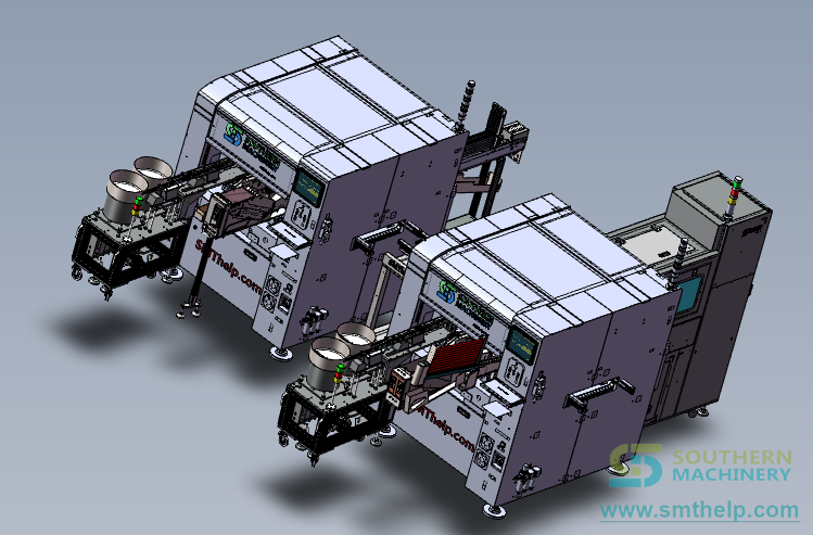
Odd-Form Insertion with Clinching: Why Clinch-Before-Wave Decides THT Yield | Southern Machinery
<iframe width="560" height="315" src="https://www.youtube-nocookie.com/embed/BSmcbr4KPAs?rel=0" title="Revolutionary 4 Heads 4 Bowl Feeders Odd-form Insertion Machine with Clinching" frameborder="0" allow="accelerometer; autoplay; clipboard-write; encrypted-media; gyroscope; picture-in-picture; web-share" allowfullscreen></iframe>
Product demo — four insertion heads, four bowl feeders and integrated lead clinching running on a THT/DIP assembly line. Source: Southern Machinery (@Smthelping).
What is this machine used for?
This is a THT odd-form insertion station with integrated clinching. It picks the through-hole parts that never fit a radial or axial tape — transformers, relays, connectors, fuse holders, terminal blocks, radial electrolytics, inductors, optoelectronic parts — orients them with machine vision, inserts their leads into the plated through-holes, and then clinches: it folds each lead flat against the solder side of the board so the component is mechanically locked in place.
The clinch is the part of the job that decides whether the rest of your THT process is repeatable. Three things in the machine title matter to a buyer:
- 4 insertion heads. Four heads work in parallel, so the insertion cycle is not limited to a single part-per-cycle rhythm.
- 4 bowl feeders. Four independently adjustable feeds (vibration bowl or tape) hold four different component families online at once — the machine is set up for a mixed part list, not a single component.
- Clinching. After the leads go through the holes, the machine bends them against the board in an inward, outward or "N" form. A clinched part cannot shift, lift or fall out while the board is transferred, fluxed and soldered. That is what turns an automatic inserter into a station you can trust to feed a wave-soldering machine.
On Southern Machinery's documented radial and terminal platforms, clinch geometry is a set of tooling parameters with published ranges — the S-3010B radial inserter specifies an "N"-type clinch base with clinch length 1.5–2.2 mm and clinch degree 10–35°, and the S7020 terminal/eyelet platform documents inward and outward clinching. Treat those as a benchmark for the class: the exact clinch form, length and orientation for your board are set by the tooling and confirmed at first article.
Southern Machinery builds this class of machine as the S-70LD / S7900 odd-form insertion platform: four heads, four adjustable feeders, industrial-PC control with lead-geometry vision, and an inline SMEMA interface so it sits on the conveyor immediately upstream of wave soldering. Documented reference figures for that platform are in the selection table below.
Typical applications
Clinch-before-wave matters most where the odd-form part is heavy, has many leads, or carries high current — exactly where a loose part is expensive:
- Power supplies, adapters and ballasts. Transformers, radial electrolytics, inductors, fuse holders and terminal blocks. A transformer can weigh enough that an unclinched part lifts or drops as the board crosses the flux wave and the solder wave; the clinch holds it down and keeps every lead seated.
- Home appliance control boards. Relays, connectors and terminal blocks on air-conditioner, microwave, induction-cooker and washing-machine PCBs — mixed component families that change between product variants, which is where a four-bowl-feeder cell pays back.
- LED drivers and lighting control. Odd-form parts on LED lighting, display and control-system boards, often running alongside a radial inserter and an auto lead cutter.
- Automotive and vehicle electronics. Car audio, vehicle power supplies and control units that mix dense SMD areas with rugged through-hole connectors, transformers and power devices that must survive vibration.
- Industrial instruments, meters, power tools and general electronics. Boards where the odd-form count per board is small but a single unseated pin becomes a functional-test failure — and rework means desoldering, cleaning the hole, reinserting and re-soldering, minutes per board.
In all of these, the manual alternative produces variable cycle times and a defect set — floating high, misinsertion, reverse insertion, hand-bent leads that bridge — that only surfaces after wave soldering and cleaning.
How it fits into a complete PCB assembly line
An odd-form inserter is one station inside the THT half of a mixed-technology line. Clinching sits at the centre of the design because of the handoff that comes next:
- SMT side (upstream): stencil printing → SPI → pick-and-place → reflow → AOI.
- Board handling into the THT section: magazine loader/destacker and SMEMA conveyor modules.
- THT insertion: axial/radial insertion (S-3010B class) for standard taped parts → odd-form insertion with clinching (this machine) for trays, bowls and tubes → terminal / pin-eyelet insertion (S7020 series) for FASTON, PIN and eyelet parts.
- Wave soldering: S-WS450 for standard wave; S-WS350B lead-free dual-wave (turbulent + laminar) where RoHS-compliant lead-free output is required — conveyor speed 0–1.8 m/min and a 3°–7° conveyor angle let you tune dwell time for the alloy.
- Cleaning and inspection: aqueous/ultrasonic cleaning of boards, pallets and fixtures (S1688, SME800, SME-5200, S-100A) → AOI / SPI / X-ray verification → depaneling (S-D601) → magazine unloader (SUL250).
Why the clinch matters here: by the time a board reaches the wave-soldering machine it has been conveyed, fluxed and preheated. A part that is only resting in its holes can lift on the flux wave or float as the solder wave passes; a part that is clinched stays down, keeps a consistent lead protrusion through the solder, and gives the wave a stable joint to form. That single mechanical step is what lets the inserter sit inline instead of the factory keeping a manual "check and press" station before the wave.
Because the machine is designed as an inline SMEMA station, it accepts boards from the existing conveyor and hands them back downstream. Existing wave-soldering, cleaning and conveyor infrastructure does not have to change — normally the deciding factor for a factory retrofitting odd-form automation onto a line that is already producing.
| Line role | Southern Machinery equipment |
|---|---|
| Standard radial insertion | S-3010B / S3000 radial insertion machines |
| Terminal / pin / eyelet insertion | S7020 series, S-7000E, S-7000T |
| Wave soldering | S-WS450; S-WS350B lead-free dual-wave |
| Feeding the odd-form cell | BF-2002D dual bowl feeder, VTF-1007 vibratory tube feeder, STF-1002 stacked tube feeder, RTF-1001 radial tape feeder |
| Board handling | Magazine loaders/unloaders, destackers, conveyor modules |
| Cleaning | S1688 / SME800 stencil cleaning, SME-5200 pallet cleaning, S-100A ultrasonic |
| Tape-waste handling | S-680A reel scrap tape cutting machine |
| Inspection | 3D SPI, AOI, X-ray |
Key selection parameters
Do not specify an odd-form inserter on head count alone. Clinch capability is the parameter most often assumed and least often verified. The "documented reference" column carries Southern Machinery's published figures for the S-70LD / S7900 odd-form platform, with clinch-geometry figures taken from the S-3010B radial and S7020 terminal platforms where the odd-form platform does not publish a number — treat them as a benchmark for the class and confirm your configuration in a formal quotation.
| Parameter to evaluate | What to ask | Documented reference |
|---|---|---|
| Clinch form | Inward, outward or "N"; is the form matched to lead diameter and pad geometry? | Inward/outward documented on S7020; "N"-type clinch base on S-3010B |
| Clinch geometry | Clinch length and clinch degree; set by tooling or programmable? | S-3010B: clinch length 1.5–2.2 mm, clinch degree 10–35° |
| Board-thickness compatibility | Min/max PCB thickness the clinch tooling supports | S-70LD: 0.8–5.0 mm PCB thickness |
| Component envelope | Body size and height, lead count, lead pitch, radial vs axial lead form | 3 × 3 to 30 × 30 mm bodies, up to 50 mm high |
| Insertion heads and feeders | Heads, and how many component families stay online without changeover | 4 heads; 4 adjustable feeders (tape or vibration plate) |
| Throughput class | Insertions/hour, and how it falls with lead count and clinch requirements | ~4,000 CPH (≈3,800 CPH radial resistor) |
| Insertion accuracy | Placement and lead-seating accuracy class | ±0.05 mm |
| Insertion force control | Force monitoring / anomaly detection; seating-depth repeatability per pin | Force-controlled seating to programmed depth |
| Vision and polarity | Lead-geometry recognition and polarity check before placement | Industrial-PC vision, polarity verified pre-placement |
| PCB handling | PCB size, thickness, conveyor direction, SMEMA inline interface | 50 × 50 to 300 × 300 mm; SMEMA inline |
| Program and data layer | Program naming/revision control, offline programming, backup policy | Industrial-PC control platform with program-file management |
| Utilities and footprint | Supply, air, consumption, noise | 220 V AC 0.8 kVA; air 0.4–0.6 MPa; ≤75 dB |
| Service and tooling | Nozzle/gripper supply, custom tooling lead time, spares, training | In-house nozzle and gripper design and manufacture |
Two field rules: send sample components with the RFQ (feeder and clinch tooling is designed from the real parts, not the part list), and agree the first-article acceptance criteria — lead penetration depth, clinch form, clinch orientation, polarity and seating — before the machine ships.
ROI and quality perspective
The case for automated odd-form insertion is not the operator's wage; it is what clinch inconsistency costs downstream.
- The hand-insertion baseline. A hand-inserted odd-form part takes roughly 4–10 seconds depending on operator familiarity and part presentation. Across a run of thousands of boards with several odd-form parts each, that variability shows up as unplanned hours that never appear in the standard cost model.
- Where the defect lands. Manual insertion produces higher rates of floating high, misinsertion and reverse insertion. On a transformer with 6–10 pins, one lead not fully seated can pass visual inspection and fail later as a field failure whose repair cost multiplies far beyond the board's assembly value. Odd-form defects are typically only caught at AOI or functional test — after wave soldering and cleaning — so rework means desoldering, cleaning the hole, reinserting and re-soldering: minutes per board and risk to neighbouring components.
- What clinching changes. A 4-head, 4-feeder cell with vision checks part orientation and polarity before placement, seats every lead to a programmed depth with controlled force, and clinches to a repeatable form. What leaves the station is what the wave encounters — consistently retained, consistently penetrated. That converts "floating high" from a normal outcome into a process escape.
- Where the fit is strongest. Medium-to-high volume per SKU (roughly 500+ boards per run, with repeat orders) and component families shared across several PCB variants. Changeover cost per SKU falls as more variants reuse the same feeders, nozzles and clinch tooling.
If you are costing an odd-form cell against a permanent manual station, price it on four lines: labour hours including overtime, rework and scrap hours, field-failure exposure, and the throughput ceiling you cannot raise without adding people.
FAQ
What is clinching in PCB assembly?
Clinching is the bending of a through-hole component's leads flat against the solder side of the board immediately after insertion, in an inward, outward or "N" form. It mechanically retains the part so it cannot shift, lift or drop before and during wave soldering.
Why clinch a part instead of simply inserting it?
An unclinched part is only held by friction in the hole. Between insertion and the solder wave the board is conveyed, fluxed and preheated — a heavy transformer or a multi-lead connector can lift or fall out. Clinching removes that failure mode and gives the wave a stable, consistently seated lead to solder.
What clinch forms are available, and how are they chosen?
Inward and outward clinch forms are documented on Southern Machinery's terminal-insertion platforms, and an "N"-type clinch base is documented on the S-3010B radial inserter (clinch length 1.5–2.2 mm, clinch degree 10–35°). The right form, length and orientation depend on lead diameter, pad geometry and board thickness, and are confirmed with the tooling at first article.
Does clinching damage the PCB or the pad?
Clinching is a controlled bend, not a punch. The risk is not the bend itself but an uncontrolled one — excessive clinch degree or force. That is why the categories to verify are clinch geometry, board-thickness compatibility and insertion force control, and why first-article acceptance should include clinch form and lead penetration depth.
How many insertions per hour can a 4-head odd-form machine do?
Southern Machinery publishes roughly 4,000 CPH for the S-70LD / S7900 odd-form platform, with lower rates for parts such as radial resistors. Real output depends on component family, lead count, presentation and clinch requirements — ask for an estimate against your actual part list and board rather than a headline number.
Can an odd-form insertion machine with clinching be added to an existing DIP line?
Yes. The machine is designed as an inline SMEMA station that takes boards from the existing conveyor and returns them downstream, positioned immediately before wave soldering. Existing wave-soldering, cleaning and conveyor infrastructure does not have to be changed.
Talk to Southern Machinery about clinch requirements
Southern Machinery (Shenzhen Southern Machinery Sales And Service Co., Ltd) has supplied SMT and THT automation equipment from Shenzhen, China since 2011, serving 237+ customers worldwide across power supply, appliance, LED, automotive and industrial electronics manufacturing.
- Send your odd-form part list, board data, clinch requirement and target volume: jasonwu@smthelp.com
- Browse the machine catalogue and 3D models: https://file.autoinsertion.com
- Machine photos, feeder and tooling close-ups: https://ph.smthelp.com
- Product and specification pages: https://www.smthelp.com
Specifications quoted above are Southern Machinery's published figures for the S-70LD / S7900 odd-form insertion platform and for the S-3010B radial and S7020 terminal platforms where clinch geometry is documented. Confirm the exact configuration, throughput, clinch form and tooling for your part list in a formal quotation.
Comments