
LED Driver Board Radial Insertion by Southern Machinery
Radial insertion for LED driver boards: S3000 capacity model, a verified 10,000 CPH actual speed, 2.5-7.5 mm component spans and complete THT line fit.
Oct 7, 2026 · Updated Oct 7, 2026 · Southern Machinery
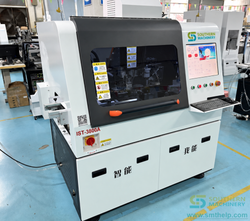
An LED driver board is a capacitor-dense through-hole assembly, and radial insertion is where its yield is decided: polarised electrolytics are tape-fed to the machine, placed at the programmed angle, clinched and lead-trimmed before the board reaches wave soldering. The S3000 radial inserter from Southern Machinery automates that step at a verified production speed of 10,000 CPH, with a 2.5-7.5 mm span range, outward or inward clinching and blade trimming to 1.5 or 2.0 mm, on a board envelope from 50 × 50 mm to 400 × 300 mm.
What is radial insertion used for on an LED driver board?
Radial insertion takes tape-packaged through-hole components, forms their leads, rotates to the programmed angle, inserts, clinches and trims. On an LED driver board the volume component is the electrolytic capacitor bank that smooths the input, surrounded by ceramic, box and film capacitors, diodes, coils and fuses.
Typical work for an S3000 in an EMS, ODM or lighting-factory setting:
- Radial electrolytic and film capacitors on LED driver and power-supply boards
- Polarised components whose orientation must be identical on every board
- Volume runs where hand-insertion pace, not machine pace, sets line output
- High-mix lines that need a stored program per board instead of a setup per board
Why does hand insertion break LED driver board assembly?
These are the failure modes the radial-insertion case is written against, all cheap on a small board and expensive at monthly volume.
Polarised capacitors fail silently when reversed
A reversed electrolytic capacitor looks correct on the bench and fails only at electrical test, or in the field. Nothing at the insertion station flags it.
The pace stops scaling with headcount
In the documented example one board carries 14 radial capacitors, so a 1,154-board shift is 16,154 hand placements — a workload that grows by hiring rather than by process.
Quality drifts where supervision is thinnest
Turnover and seasonal staffing reintroduce exactly the placement errors the work instruction was written to prevent, and they cluster on lightly supervised shifts. Manual stations also leave no record of which component, from which reel, went into which board.
How much radial capacity does one S3000 cover on a 2-up LED driver panel?
This is not a general throughput claim: it is the capacity arithmetic for one stated board, with the customer-supplied inputs labelled.
Formula: radial capacity per shift = (boards per shift × radial components per board) ÷ verified production speed
Worked example — every figure below is an example, depends on configuration, and is subject to final technical confirmation:
- Board — example 180 × 120 mm, 1.6 mm thick, run 2-up as a 360 × 120 mm panel
- Monthly volume — example 60,000 boards, 26 days, 2 shifts
- Radial components per board — example 14 capacitors
- Speed — 10,000 CPH actual, the figure Southern Machinery quotes rather than the peak
- Boards per shift — example 1,154, giving example 16,154 insertions
- Machine time — example about 1.6 hours, roughly 16% of a 10-hour shift and about six times the headroom the current volume needs
Both fit lines sit inside the published envelope: the panel is within the 50 × 50 – 400 × 300 mm PCB range, and 1.6 mm within the 0.79 – 2.36 mm thickness range.
How does the S3000 connect to a complete PCB assembly line?
Radial insertion is one station in a five-step through-hole flow, and normally the step still manual when everything else is automated.
Upstream: SMT printing, placement and reflow
Driver boards are printed, populated and reflowed first, with control and LED-side parts in the SMT section — catalogued at smthelp.com/product-category/smt-machine.
The radial step itself
Radial components are inserted at a programmable 0-360 degree angle, clinched outward or inward where bottom-side density would risk shorting in the wave, then trimmed. The THT family is at smthelp.com/product-category/tht-machine and the machine at smthelp.com/the-s-3000-radial-auto-insertion-machine.html.
Board handling in and out of the cell
An optional PCB loader and unloader with a T-type material station saves floor space and keeps bare boards off the operator's hands — see smthelp.com/product-category/board-handling-system.
Downstream: wave soldering, then inspection
Clinch direction, lead length and insertion angle decide bridging and joint quality before the board reaches the wave — see smthelp.com/wave-soldering-machine.html and the combined dip-soldering flow at smthelp.com/pcb-dip-assembly-line.html.
Which S3000 specifications decide whether it fits your LED driver board?
The source tags every value with the file it came from and records where the two Southern Machinery sources disagree. Both are carried below; the conservative value is used above.
- Model and size — S3000 radial inserter, 1700 × 1500 × 1600 mm, 880 kg
- PCB size and thickness — 50 × 50 mm minimum; 400 × 300 mm maximum on the product page, 450 × 450 mm on the datasheet; 0.79 – 2.36 mm thick
- Production speed — 10,000 CPH actual; spec speed 18,000 CPH (datasheet) against 20,000 CPH (product page)
- Component spans — 2.5, 2.5 + 5.0 and 2.5 + 5.0 + 7.5 mm (datasheet), against up to 10.0 mm quad span (product page)
- Component envelope — 20 mm body height; 10 mm body diameter (datasheet) against 13 mm (product page); 0.7 mm maximum lead diameter
- Insertion angle and clinch — 0 – 360 degrees in 1 degree increments; outward clinch standard, inward option
- Lead trim and bend — 1.5 ± 0.3 mm short blade, 2.0 ± 0.3 mm long blade; 10 – 15 degrees adjustable
- Feeder inputs — 20 to 100 expandable (datasheet) against 10 recommended stations (product page); possibly different units of measure
- Insertable components — electrolytic, ceramic, box and film capacitors, transistors, diodes, LEDs, connectors, tact switches, coils, potentiometers, lamps, fuses
- Programming and utilities — off-line programming with USB input; 220 V, 50 Hz single phase; air at 0.6 – 0.8 MPa; built-in air storage and 3 KVA regulator
- Wear parts and certification — Universal-compatible wear parts; radial and axial inserters obtained CE certification in 2010
Anything not listed is not specified in the source document. The running-cost line shows why that matters: the datasheet quotes RMB 2,000 per month per unit against under 100 USD per month on the product page, a three-fold gap that may cover different scopes. Quote neither until engineering confirms.
What stays outside the S3000's radial scope?
Radial insertion does not cover every through-hole component on a driver board, and the case document is explicit about the split.
- Radial capacitors — 14 per board in the example, inside the S3000's span and body-height range
- Axial components — 6 resistors per board; an axial insertion class, seen at smthelp.com/s4000-axial-auto-insertion-machine-for-pcb-assembly.html
- Terminals and odd-form parts — 4 per board; outside the S3000's scope, in the odd-form class at smthelp.com/odd-form-insertion-machine.html
- Wave soldering, AOI and electrical test — existing or quoted separately; radial insertion changes their defect input, not their specification
What does the payback calculation still need from you?
Capacity lines are computable from a board layout. Money lines are not, which is why the source model leaves them open instead of filling them with industry averages.
Formula: payback period = total investment ÷ monthly net saving, where monthly net saving = (operators avoided × shifts × loaded hourly rate) + (defects avoided per month × unit value) − (running cost + wear parts)
- Operators avoided per shift — example 3, as stated in the customer brief
- Loaded hourly rate, measured manual defect rate and investment figure — not specified in the source document; your own figures are required
No payback figure is quoted here because those inputs are yours. The mechanism is what matters: a machine whose radial work occupies about 16% of a shift is judged on the labour and scrap it removes from the other 84%.
FAQ: questions buyers ask before ordering an LED driver radial inserter
Can the S3000 insert the capacitors on an LED driver board?
Yes. It inserts radial tape-packaged capacitors — electrolytic, ceramic, box and film — plus transistors, diodes, LEDs, connectors, tact switches, coils and fuses.
Does my panel fit?
A 360 × 120 mm 2-up panel fits the 400 × 300 mm product-page envelope and the 450 × 450 mm datasheet one, with 1.6 mm inside the thickness range.
How much of my shift does the radial work take?
In the documented example, 1,154 boards at 14 capacitors each is 16,154 insertions — about 1.6 hours at 10,000 CPH actual, or roughly 16% of a 10-hour shift.
Can I run axial resistors and terminals on the same machine?
No. Radial components are the S3000's scope; axial resistors and terminal or odd-form parts need separate insertion classes.
Will I be locked into proprietary spare parts?
The product page states compatibility with Universal machine wear-and-tear parts, with a quoted 1-day spare-part lead time. Running-cost scopes differ between sources, so confirm them first.
What utilities and floor space does it need?
220 V, 50 Hz single phase and air at 0.6 – 0.8 MPa with built-in storage and a 3 KVA regulator, on a 1700 × 1500 × 1600 mm footprint at 880 kg.
Next step: send your LED driver panel layout for a capacity model
Tell us which driver boards you insert, the radial components you run and your monthly volume. You get a configuration, a capacity model and a delivery schedule within 24 hours, with the labour and yield lines completed from your numbers rather than guessed. Southern Machinery has built SMT and THT PCB assembly automation from Shenzhen since 2011 and serves more than 237 customers worldwide; the line proposition is at smthelp.com/one-stop-pcb-assembly-total-solutions-for-ems.html, the catalogue at file.autoinsertion.com, and machine photos at ph.smthelp.com.
Comments