
Board Insertion by Component Insertion Machines: A Practical THT Process Guide | Southern Machinery
THT assembly is not finished when the SMD side leaves reflow. Every mixed-technology board still carries leaded capacitors, resistors, LEDs, relays or connectors that must be inserted into plated holes with the right position, angle and force. This practical guide for SMT and THT line engineers covers the component insertion machine board-insertion workflow — preparation, positioning and insertion force, per-component parameter setting, and post-insertion inspection — plus typical applications, full-line integration, key selection parameters and ROI. Southern Machinery, Shenzhen, 237+ global customers.
Sep 25, 2026 · Updated Sep 25, 2026 · Southern Machinery
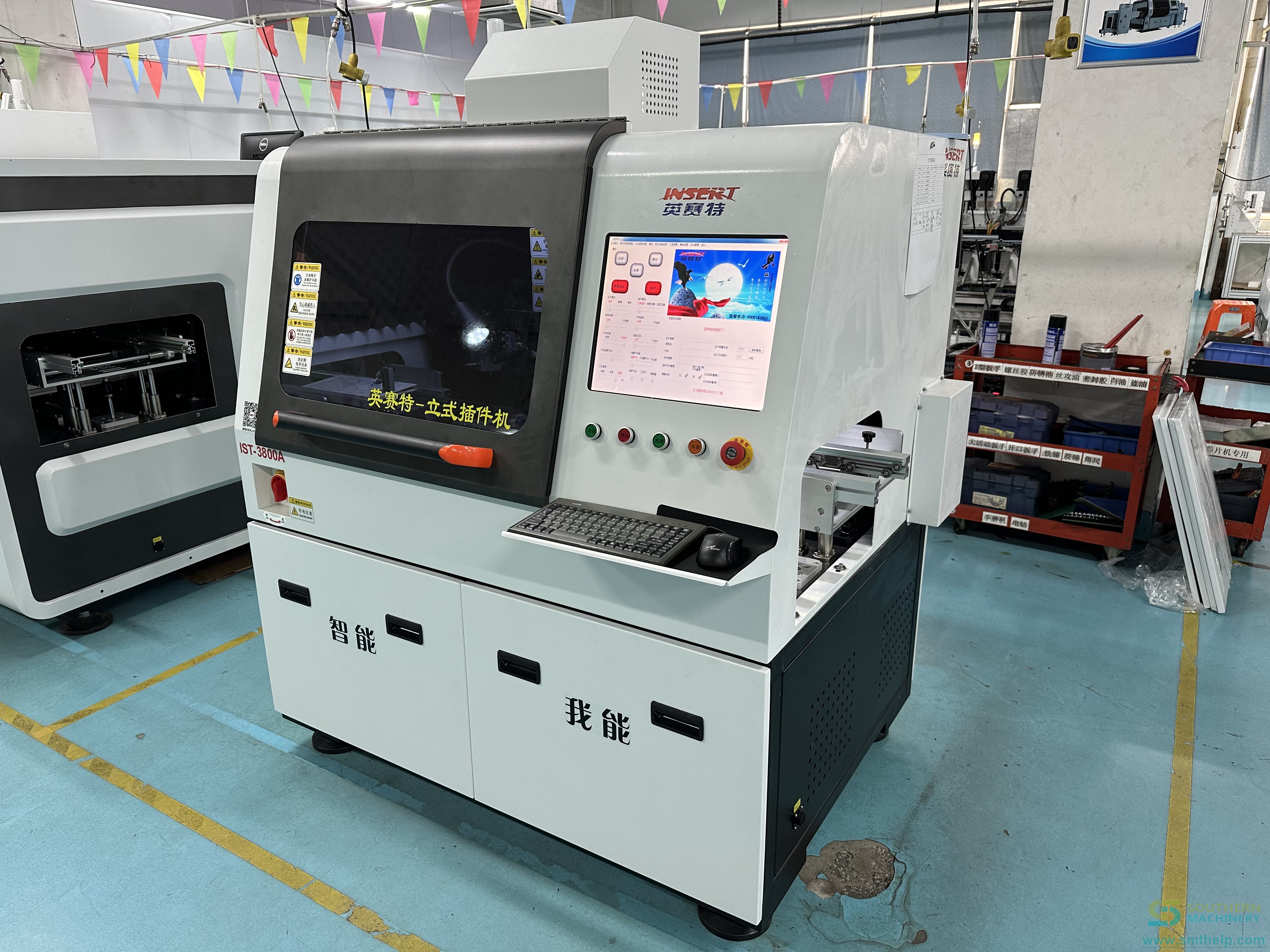
Board Insertion by Component Insertion Machines: A Practical THT Process Guide | Southern Machinery
Through-hole (THT) assembly is not finished when the SMD side leaves the reflow oven. Every mixed-technology board still carries radial capacitors, axial resistors, LEDs, relays, connectors, transformers or eyelets — and each one has to be driven into a plated hole with the right position, the right angle and the right insertion force. The component insertion machine owns that step, and the quality of the board-insertion process decides whether those parts survive wave soldering or reappear later as missing insertion, wrong insertion and poor soldering.
This guide covers the board-insertion workflow that an SMT/THT line engineer actually has to control, and shows where an automatic insertion machine sits inside a complete PCB assembly line.
Watch: board insertion by component insertion machines
<iframe width="560" height="315" src="https://www.youtube-nocookie.com/embed/iJr1dSXSmNk?rel=0" title="Guide to Board Insertion by Component Insertion Machines" frameborder="0" allowfullscreen></iframe>
What is board insertion by component insertion machines used for?
Board insertion is the automated process of feeding a through-hole component from a tape, reel, tube, tray or bowl feeder, indexing the PCB to a reference position, and pressing the component leads through the correct plated holes — then clinching (bending) those leads underneath so the part stays seated through wave soldering.
A component insertion machine replaces the manual THT bench. The operator no longer picks a capacitor out of a bin, reads the silkscreen and pushes it into the board by hand. Instead the machine repeats one sequence every cycle:
- Index the PCB to a repeatable reference position.
- Feed the component to the insertion head in a known orientation.
- Drive the lead(s) into the hole at a controlled insertion force.
- Clinch the lead to hold the part in place for soldering.
The payoff is repeatability. Manual insertion is a human judgement call repeated thousands of times per shift; automatic insertion is the same motion every cycle, which is what makes first-pass yield predictable — and auditable.
Before the first board — preparation. This is where most board-insertion problems are either created or prevented:
- Study the documentation. Operators need the PCB design drawings and the component list (BOM) to identify the specification, model and insertion position of every part.
- Debug the machine. Confirm the feeding system delivers components reliably to the insertion position, and calibrate the motion accuracy of the positioning and insertion head so components land precisely in the holes.
- Confirm the board will locate. Correct loading and location — silkscreen orientation, positioning holes and track seating — is covered in detail in our companion guide, How to install PCB boards onto SMT insertion machines.
During insertion — monitor two things. Positioning accuracy and insertion force. If the head misaligns, or the part meets unexpected resistance, stop the machine and inspect instead of pushing through. One misaligned insertion damages both the component and the PCB, and a scrapped board costs far more than the few seconds you save by ignoring the alarm.
Set parameters per component family. Precision or small-body parts are inserted at a reduced speed to protect accuracy; regular resistors and capacitors can run faster where quality allows. Separating the accuracy-critical parts from the throughput-friendly parts in the program is one of the simplest ways to raise both yield and output.
After insertion — inspect and feed back. A timely quality check catches missing insertion, wrong insertion (including reversed polarity) and poor lead seating that would otherwise only surface as a wave-soldering defect. Record the defect, find the root cause, and adjust the program parameters or the operating procedure. That loop — inspect, analyse, adjust — is what continuously improves board-insertion reliability.
Typical applications
Automatic board insertion pays back fastest wherever a board carries a repeating set of leaded parts at moderate-to-high volume.
- Power supplies and adapters. Radial electrolytic capacitors and axial resistors inserted in fixed positions, then clinched ahead of wave soldering. High part counts per board make manual insertion a bottleneck.
- LED lighting and driver boards. Radial LEDs and capacitors are a classic radial-insertion application; consistent orientation and seating matter because a lifted LED shows up as an open after the wave.
- Home appliance control boards (air conditioners, washing machines, induction cookers, microwaves). Mixed radial parts plus odd-form relays, transformers and connectors — often the highest-labour THT content on the board.
- Automotive and vehicle electronics (car audio, vehicle power supplies). Higher mix, tighter traceability: inserted-part records support the quality documentation these programs demand.
- Instruments and general electronics (meters, watches, control modules). Lower volume but repetitive THT content, where one program replaces a manual bench and its variability.
How it fits into a complete PCB assembly line
Board insertion is one block in an end-to-end PCB assembly flow, and it works best when the blocks are sized to the same takt:
- SMT block: solder-paste printing → SPI → pick-and-place (chip mounter) → reflow → AOI. SMD parts are placed and reflowed first.
- THT insertion block: axial and radial automatic insertion machines (for tape-packed resistors, capacitors, transistors, LEDs and key switches), followed by an odd-form / pin-eyelet-terminal insertion machine for parts that radial and axial inserters cannot handle.
- Wave soldering block: the inserted board passes over flux, preheat and the wave, where the clinched leads are soldered. A lead that was not seated properly during insertion becomes a cold joint or a skip here.
- Inspection and handling block: AOI / SPI, X-ray, plus board handling (magazine loaders and unloaders) and cleaning equipment to move and clean boards without edge damage.
In other words, the board-insertion step is the bridge between SMT and wave soldering. Its output quality is not optional — it directly sets the wave-soldering yield.
Documented Southern Machinery platforms for this step:
- S-3010B Radial Insertion Machine (off-line): rated up to 22,000 CPH (approximately 13,000 CPH in production); lead spans of 2.5 / 5.0 / 7.5 / 10.0 mm; 0°–360° insertion direction in 1° increments; servo-driven 13.0 mm insertion head with an "N"-type clinch base; clinch length 1.5–2.2 mm at 10–35°; components include capacitors, transistors, LEDs and key switches; PCB up to 400×400 mm, 0.79–2.36 mm thick; machine-vision correction; English/Chinese interface.
- S3000 Automatic Radial Component Insertion Machine: maximum mechanical speed up to 18,000 CPH with typical production throughput of approximately 10,000 CPH; supports 2.5 mm and 5.0 mm lead spans; 0–360° insertion direction at 1° increments; machine vision for position correction; automatic lead cutting and clinching; offline programming; PCB up to 400×380 mm, 0.79–2.36 mm thick.
- S-70LD Odd Form Insertion Machine: 4 heads; up to 4,000 CPH (3,800 CPH on radial resistors); ±0.05 mm placement; components from 3×3 mm to 30×30 mm and up to 50 mm high; vision-based lead and polarity verification; SMEMA inline, positioned immediately upstream of wave soldering; PCB 50×50–300×300 mm, 0.8–5.0 mm thick.
- S7020 / S-7000E pin, eyelet and terminal insertion machines: 12,000 CPH class, 1–4 insertion heads, components in the 1.3–4.0 mm range, PCB up to 480×390 mm — for terminals and eyelets that neither radial nor axial inserters can place.
(All figures above are vendor-published parameters. Confirm them against the datasheet for the exact model and configuration you are buying — feeds, heads and PCB size are usually configurable.)
Key selection parameters
When you evaluate an automatic insertion machine, these are the categories that decide whether it fits your boards:
| Parameter | What to check |
|---|---|
| Component family and packaging | Radial tape, axial tape, bulk, reel, tube, tray or bowl feed — and which part families the machine accepts. |
| Lead span / pitch range | The pitch and lead diameter range your board actually uses; a machine that spans too narrow a range will not cover your BOM. |
| Insertion speed and real throughput | Distinguish maximum mechanical CPH from typical production CPH — your planning number is the second one. |
| Insertion angle and rotation | Programmable insertion direction (e.g. full 360° in 1° steps) for parts that must be oriented to the silkscreen. |
| Position correction | Machine-vision or mechanical correction for board and component position, so insertion lands in tolerance across the panel. |
| Clinch capability | Inward, outward or "N"-type clinching, plus clinch length and angle, matching the lead length and hole design. |
| PCB size and thickness | Minimum and maximum board dimensions and thickness range vs. your largest and thickest product. |
| Feeder count and changeover | Number of feeders and how quickly the program and feeder setup change between products — the high-mix bottleneck. |
| Programming and data | Offline programming, program library, visual programming, data import/export (e.g. Excel/USB) and MES connectivity. |
| Line integration | SMEMA compatibility and loader/unloader readiness so insertion slots into the existing line. |
| Utilities and footprint | Air pressure and consumption, power, and machine footprint against your available floor space. |
ROI and quality perspective
From a buyer's point of view, the case for automatic board insertion is not "automation is modern" — it is arithmetic.
- Labour. Manual THT insertion typically consumes seconds per part, and those seconds multiply across thousands of boards and multiple shifts. Southern Machinery's published THT analysis describes manual odd-form insertion running 4–10 seconds per part, with 8–16 hours of unplanned labour per shift on a 5,000-board run carrying four odd-form parts each. An insertion machine converts most of that time into machine time.
- Rework and scrap. Manual insertion defects — parts not fully seated, reversed orientation, missed holes — are discovered after wave soldering, where rework commonly takes 3–5 minutes per board. Automated insertion with vision verification and controlled insertion force removes the largest source of those defects, and the field cost of a defect that escapes inspection is typically 20–50× the board value.
- Consistency and traceability. A machine inserts the same way every cycle and can log what it did. That consistency is what lets you commit to a first-pass-yield number, and the data supports the quality documentation that appliance, automotive and power-supply customers increasingly require.
- Changeover economics. The traditional objection to automatic insertion is high-mix, low-volume work. Program-based changeover with quick-change feeders is what makes the machine viable for mixed production, not just mass runs.
The honest way to evaluate ROI is to take your own board: count the THT parts, measure the manual seconds per part, and multiply by your annual volume and loaded labour rate — then compare against the machine's cost, its real production CPH and its changeover time.
FAQ
What is board insertion in PCB assembly?
Board insertion is the step where through-hole (THT) components are placed into the plated holes of a PCB and their leads are clinched underneath, before the board goes over the wave-soldering wave. In automated assembly, a component insertion machine feeds, positions and inserts the parts instead of an operator doing it by hand.
What is the difference between axial and radial insertion?
Axial components (like many resistors and diodes) have leads at opposite ends of the body; radial components (like electrolytic capacitors and LEDs) have leads on the same side. Axial and radial insertion machines are built around those different body geometries and feeding formats, so most THT lines use both.
What is odd-form insertion and why does it need a separate machine?
Odd-form components — relays, connectors, transformers, eyelets, pin terminals — do not fit the standard axial or radial tape format. An odd-form or pin/eyelet-terminal insertion machine handles them with vision-guided, force-controlled placement, which is why it usually sits alongside the radial inserter on the line.
Which parts can a component insertion machine actually insert?
Typical radial and axial machines handle tape-packed resistors, capacitors, transistors, LEDs and key switches. Odd-form and terminal machines extend that to relays, connectors, transformers, eyelets and PIN terminals. Confirm the component list against the specific machine's published component range.
What causes missing insertion, wrong insertion or poor soldering?
Common root causes are incorrect PCB location or orientation, board holes drilled out of tolerance, wrong program coordinates, machine zero/offset out of tolerance, worn tooling, and an insertion force set too high or too low. Correct preparation, positioning and parameter settings prevent most of them, which is why the inspection-and-feedback step matters.
How do I know if automatic insertion is worth it for my plant?
Count the THT parts per board, measure your current manual seconds per part, and multiply by annual volume and loaded labour cost. If the manual hours, plus rework and defect cost, exceed the machine's total cost of ownership over your payback window, automation pays. For mixed production, factor in program changeover time.
Talk to Southern Machinery about your THT insertion step
Southern Machinery (Shenzhen, China, founded 2011) provides automatic insertion machines, wave soldering equipment, board handling and peripheral equipment to 237+ customers worldwide, with service, spare parts, training and retrofits behind every machine.
- Send us your board — component list, board size and annual volume — and we will recommend the right insertion configuration. Email jasonwu@smthelp.com or call +86 13602562576.
- Browse the machine catalog at file.autoinsertion.com.
- See machine photos and line layouts at ph.smthelp.com.
- More technical guides on SMT, THT, wave soldering and PCB assembly automation at smthelp.com.
Comments