
Four-Head Component Inserter: The Throughput Engine of a THT Assembly Line | Southern Machinery
A DIP line is only as fast as its slowest station, and that station is usually the manual odd-form insertion bench — transformers, relays, connectors and terminal blocks placed by hand at 4 to 10 seconds per part. This guide explains what a four-head component inserter is, how four parallel insertion heads change the takt of the THT block, and where the machine sits between board handling, radial insertion, wave soldering and AOI. It covers five real application scenarios, the selection parameters that decide fit, and the return-on-investment case for automating odd-form insertion. From Southern Machinery, established 2011 in Shenzhen, China, serving 237+ EMS and OEM electronics manufacturers worldwide with SMT and THT PCB assembly automation.
Sep 28, 2026 · Updated Sep 28, 2026 · Southern Machinery
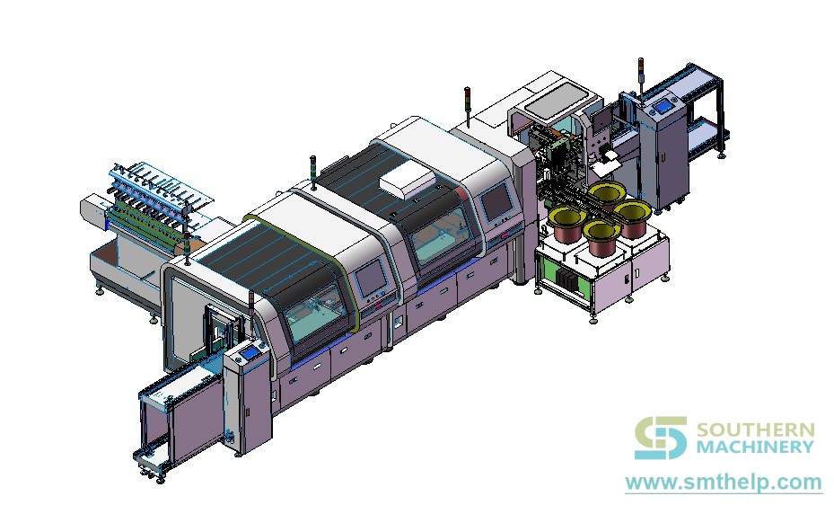
Four-Head Component Inserter: The Throughput Engine of a THT Assembly Line
A DIP line's output is set by its slowest station, and in most EMS factories that station is the manual insertion bench at the end of the THT (through-hole technology) section. Operators hand-place transformers, relays, connectors, fuse holders and terminal blocks — parts that do not come on radial or axial tape — while a wave soldering machine waits downstream.
A four-head component inserter changes that equation. Not because any single insertion head is dramatically fast, but because four heads work in parallel while the board indexes through the station. Head count, feeder architecture and program quality — not operator skill — become the variables that decide how many boards leave the line per shift.
This article looks at the four-head inserter as the capacity engine of a THT line: what it does, where it fits, how to size it and how to judge the return.
<iframe width="560" height="315" src="https://www.youtube-nocookie.com/embed/i7OYHHudOb4?rel=0" title="The SMT four-head component inserter: The Efficient Engine for Factory Production" frameborder="0" allow="accelerometer; autoplay; clipboard-write; encrypted-media; gyroscope; picture-in-picture" allowfullscreen></iframe>
Video: The SMT four-head component inserter — the efficient engine for factory production (@Smthelping, Southern Machinery).
---
What is this machine used for?
A four-head component inserter is an automated THT insertion station that places non-standard, "odd-form" through-hole components onto a PCB using four independent insertion heads. Each head carries its own nozzle or gripper and picks from its own feeder, so four different part types can be presented, oriented and seated in overlapping motion rather than one after another.
It is the answer to a specific production problem: the components that fall outside the radial/axial tape feeders. Think transformers, relays, E-caps, inductors, connectors, fuse holders, terminal blocks and optoelectronic parts in trays, tubes, sticks or loose bulk. Most factories assume these must be inserted by hand. That assumption is what makes the last stations of the DIP line the quiet bottleneck.
In practice, a four-head inserter is used for:
- Replacing the manual odd-form insertion bench at the end of a DIP line
- Placing multiple odd-form part types in one pass without a tooling change
- Removing the throughput variability that comes with operator turnover and shift changes
- Feeding a wave soldering machine with boards whose components are consistently seated to depth
Unlike a chip mounter on the SMT side, the inserter works on leaded parts with real insertion force — which is why head mechanics, feeder presentation, vision alignment and force control matter more than raw pick-and-place speed.
---
Typical applications
Four-head odd-form insertion pays back fastest where a small, stable family of non-standard parts repeats across many boards. Five common scenarios:
- Power supplies and adapters — transformers, radial electrolytic capacitors, terminal blocks and input/output connectors on switching power supply boards.
- Home appliance control boards — relays, rectifiers, connectors and E-caps on air-conditioner, TV, microwave and small-appliance PCBs.
- LED drivers and lighting boards — radial E-caps, inductors, terminal blocks and MOV/varistor parts on driver PCBs and luminous-character control boards.
- Automotive and vehicle electronics — fuse holders, relays, connectors and terminal blocks on car-audio, vehicle power supply and body-electronics boards.
- Industrial instruments and control boards — terminal blocks, opto parts, switches and sensor connectors on instruments, meters and machinery controllers.
In every case, the pattern is the same: medium-to-high volume per model, four to eight odd-form placements per board, and a part family that repeats from one PCB variant to the next.
---
How it fits into a complete PCB assembly line
A four-head inserter is not a standalone machine — it is a station in a line, and its value is decided by what sits upstream and downstream of it. The typical flow:
| Line block | Stations | What happens |
|---|---|---|
| SMT block | Solder paste printer → SPI → pick & place (chip mounter) → reflow → AOI | SMD components are printed, placed and reflowed |
| Board handling | Loader → conveyor → shuttle / buffer / flipper | Boards enter the THT section in a controlled flow (SMEMA handshake) |
| Axial & radial insertion | Axial inserter → radial inserter | Standard leaded parts placed automatically |
| Odd-form insertion | Four-head component inserter | Non-standard parts placed in parallel, with vision alignment and controlled insertion force |
| Terminal / pin / eyelet | Terminal inserter, PIN/eyelet inserter | FASTON terminals, pins, eyelets and odd-form terminals placed and clinched |
| Soldering | Wave soldering (lead-free or standard) | Through-hole joints are formed |
| Cleaning | PCBA / pallet / stencil cleaning | Flux residue and contamination removed |
| Inspection | AOI, SPI, X-ray | Solder joints, placement and hidden joints verified |
| End of line | Depaneler (e.g. LED MCPCB separator) → magazine unloader | Boards separated and stacked for the next stage |
Why the four-head station is the engine. Everything downstream — wave soldering, cleaning, inspection — runs at a fixed takt. If the odd-form station is slower than that takt, the whole THT block runs at the inserter's pace. Adding insertion heads, matching feeders to the real part mix and moving programming offline are the levers that raise that ceiling without adding operators, shifts or floor space.
The inserter is also designed to be a retro-fit station: it accepts boards over the line conveyor via SMEMA handshake and sits upstream of the existing wave soldering machine, so an existing DIP line gains automation without replacing its soldering, cleaning or conveyor infrastructure. For standard radial components on the same line, a radial insertion machine (for example the S-3010B or S3000 class) covers the tape-fed side; the four-head inserter covers everything the tape feeders cannot.
---
Key selection parameters
The parameters below are the ones that decide whether a machine fits your board. The right-hand column gives the published figures of a documented platform in this class (Southern Machinery S-70LD / S7900 odd-form inserter) purely as a reference point — the specific configuration you buy must be confirmed against your own component list.
| Parameter | What to evaluate | Documented reference (S-70LD / S7900 class) |
|---|---|---|
| Insertion heads | Number of independent heads = the parallelism of the station | 4 heads |
| Feeder positions | How many feeders can be mounted, and which types (tape, vibratory bowl, tube, tray) | 4 feeders, tape or vibration plate, adjustable |
| Component envelope | Smallest / largest body size and maximum component height | 3×3 mm to 30×30 mm, up to 50 mm high |
| Placement accuracy | Repeatability of the insertion position across a run | ±0.05 mm |
| Throughput class | Rated placements per hour for the machine class (always confirm with your component mix) | 4,000 CPH class; ≈3,800 CPH for radial resistor insertion |
| Component presentation | Can it take your real packaging — bulk, tube, tray, reel, bowl? | Tape or vibratory-plate feeding, adjustable feeder positions |
| Clinching | Whether the machine clinches leads to hold parts before wave soldering | Available on the S7900IV-W configuration |
| Vision / polarity | Lead-geometry recognition and polarity check before placement | Industrial-computer vision guidance; rejects 180°-rotated parts |
| Insertion-force control | Consistent seating depth per lead, regardless of component tolerance | Constant insertion force, every lead to programmed depth |
| PCB size & thickness | Minimum / maximum board and board thickness range | 50×50 mm to 300×300 mm; 0.8–5.0 mm |
| Line interface | SMEMA handshake, conveyor direction, inline or off-line operation | SMEMA inline station upstream of wave soldering |
| Program & data layer | Offline programming, program library, revision control, MES/traceability link | Industrial PC control; programmable insertion orientations |
| Utilities & footprint | Power, air and floor loading | ~1,000 kg; 220 V AC, 0.8 kVA; air 0.4–0.6 MPa; ≤75 dB |
Caveat: the values in the right-hand column belong to a documented Southern Machinery platform and are published here as a benchmark for the class. They are not a specification for every machine configuration or for the machine shown in the video. Always confirm head count, feeder count, component envelope and throughput against your actual BOM.
---
ROI and quality perspective
The business case for a four-head inserter is not "machines are faster than people." It is that manual odd-form insertion has a cost structure that never appears on the payroll report.
The published Southern Machinery analysis of manual odd-form insertion puts three invisible penalties on the table:
- Throughput variability — a hand-inserted connector takes roughly 4 to 10 seconds depending on operator familiarity, part orientation and how the part is presented. Over a run of 5,000 boards with 4 odd-form components each, that spread can add an estimated 8 to 16 hours of unplanned labour per shift.
- Defect rate — manual insertion consistently produces more floating high (not fully seated), misinsertion (wrong orientation) and reverse insertion (polarity) defects than machine insertion.
- Rework cost — odd-form defects are usually only caught at AOI or functional test, after the board has already passed wave soldering and cleaning. Rework means desoldering, cleaning the through-holes, reinserting and re-soldering: roughly 3 to 5 minutes per board, with a risk of damaging adjacent components.
The fourth number is the one that ends most debates: on a transformer with six to ten pins, a single non-seated pin can cause a field failure that costs 20 to 50 times the board's assembly value to repair. That is a warranty and reputation cost, not a labour cost.
What a multi-head inserter changes:
- Consistent cycle time. Parallel heads and fixed feeder presentation remove the operator-to-operator spread. Capacity per shift becomes a machine parameter you can plan against, not an estimate.
- Consistent insertion force. Every lead is seated to the same programmed depth, every cycle — which is exactly what eliminates floating-high defects.
- Polarity checked before placement. The vision system identifies lead geometry and rejects a part presented rotated 180°, so reverse insertion never reaches wave soldering.
- Capacity without headcount. The number of heads is the capacity lever. Raising output by adding a shift adds wage, training and variability cost; the same output can come from a machine whose heads and feeders are matched to the part mix.
- Program discipline becomes an asset. Once insertion programs, feeder positions and component data are managed as controlled documents (with revision control and backup), changeover between similar boards shrinks and first-article verification shortens.
The strongest-fit profile is a factory running a repeating odd-form part family across several PCB variants, medium-to-high volume per SKU, and a DIP line that is already wave-soldered and inspected — the inserter is the missing automated station between radial insertion and the wave.
---
FAQ
How many components per hour can a four-head component inserter place?
Throughput is a function of head count, the cycle time for the specific component, feeder presentation and how many insertions are needed per board — not a single universal number. As a reference point, Southern Machinery's documented four-head odd-form platform (S-70LD / S7900 class) is published at the 4,000 CPH class, with approximately 3,800 CPH for radial resistor insertion. Your figure must be calculated from your own component mix.
What types of components can a four-head inserter place?
Non-standard through-hole parts that do not fit radial or axial tape: transformers, relays, connectors, fuse holders, terminal blocks, radial electrolytic capacitors, inductors, and optoelectronic parts. Feeders must be matched to how your parts actually arrive — tape, tube, tray or bulk.
How does a four-head machine differ from a single-head odd-form inserter?
A single-head machine places one component per cycle, so its takt is set by the slowest part in the BOM. With four heads, four different parts can be picked, oriented and seated in overlapping motion; each head can be assigned its own feeder and its own nozzle or gripper. The result is a lower, more predictable cycle time per board rather than lower cycle time per part.
Can a four-head inserter be retrofitted into an existing DIP line?
Yes — the class is designed to be an inline station. It accepts boards over the line conveyor via SMEMA handshake and sits upstream of the existing wave soldering machine, so soldering, cleaning and conveyor infrastructure do not have to be replaced. Line direction, conveyor height and available space are the checks to confirm first.
How do I decide how many heads and feeders I need?
Start from the board, not the machine: list the odd-form components, their body sizes, how each is packaged, and how many placements per board. The part with the longest cycle time and the tightest feeder requirement sets the floor. Then compare the total insertion time per board against the takt of the wave soldering and inspection stations downstream — the difference tells you whether you need more heads, more feeder positions, or offline programming.
Does a four-head inserter replace the manual insertion bench completely?
For a stable, repeating odd-form part family, yes — that is its purpose. For very low-volume, high-mix work with constantly changing parts, the economics are better assessed case by case, because feeder and nozzle tooling has to be engineered for each part family.
What should I send Southern Machinery for a configuration proposal?
Your odd-form component list with body dimensions and packaging, PCB size range and thickness, target boards per shift, the existing line layout (or the planned one), and the downstream wave soldering and inspection stations. With those, a specific head/feeder configuration can be proposed and the return calculated against your own labour rate and volume.
---
Next steps
Southern Machinery has been designing and manufacturing SMT and THT auto insertion equipment in Shenzhen, China since 2011, and serves 237+ global EMS, ODM, automotive and medical electronics manufacturers. The range covers the full PCB assembly line: automatic insertion machines (axial, radial, odd-form, pin/eyelet/terminal), wave soldering, board handling, cleaning, depaneling and inspection equipment.
- Talk to a specialist: [jasonwu@smthelp.com](mailto:jasonwu@smthelp.com) — send your odd-form component list, PCB size range and target volume.
- Browse the catalog: file.autoinsertion.com
- See machine photos: ph.smthelp.com
- Watch more line videos: YouTube /c/Smthelping
- Product information: smthelp.com
---
Published by Southern Machinery — SMT/THT PCB assembly automation lines. Established 2011 in Shenzhen, serving 237+ global EMS, ODM, automotive and medical electronics manufacturers.
Comments