
ESD Tray with Grids for THT Kitting by Southern Machinery
An ESD tray with grids keeps every through-hole part number in its own pocket instead of a shared bin. The configuration on the assembly drawing measures 457 x 289 mm inside and 45 mm deep, and three long plus four short fluted dividers make 20 cells at about 91 x 72 mm. Because the dividers are separate parts, one tray covers several BOMs, cuts kitting time and removes the mixed-value defects that pass in-circuit test and fail at final assembly. Surface resistivity of 10 to the 4th to 10 to the 8th ohm to IEC 61340-5-1 is stated for the range, and the six open points are published rather than averaged away.
Sep 28, 2026 · Updated Sep 28, 2026 · Southern Machinery

ESD Tray with Grids for THT Kitting by Southern Machinery
Short answer: An ESD tray with grids is a conductive anti-static component tray that keeps each part number in its own pocket during kitting, storage and line-side feeding in THT and mixed SMT/THT PCB assembly. The configuration on the assembly drawing supplied with this enquiry measures 457 x 289 mm inside, 45 mm deep, and three long plus four short fluted dividers make 20 cells at about 91 x 72 mm. Because the dividers are separate parts, one tray shell covers several BOMs — a different grid is a different divider set, not a different tray.
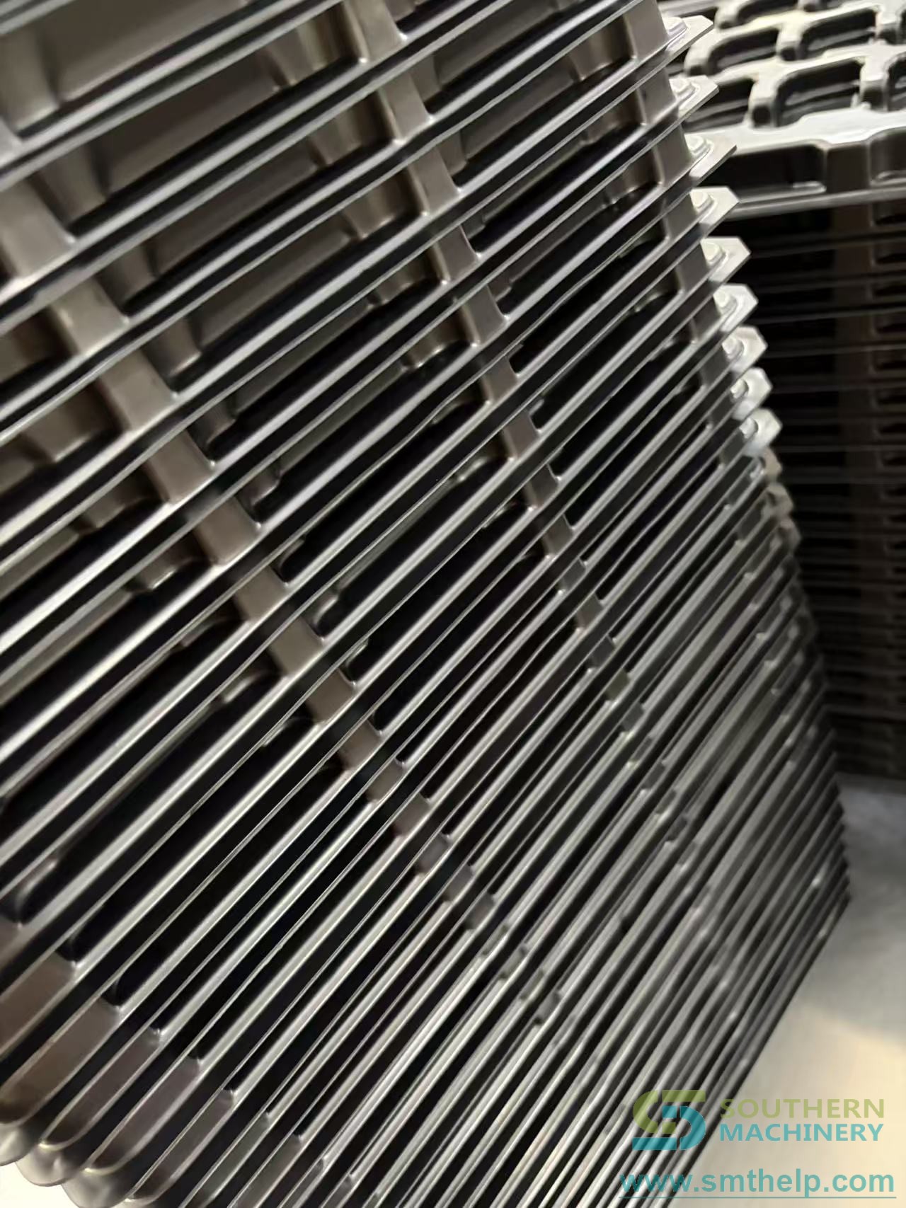
What is an ESD tray with grids used for in THT assembly?
Kitting at the insertion line
The tray is loaded at the kitting bench and travels with the job. Operators pick from labelled cells instead of a shared bin, and the same container carries the parts to the machine. On a THT line running axial, radial and odd-form inserters, it sits between incoming inspection and the first insertion station.
Line-side and between-operation storage
Trays stack and nest. The published range describes corner posts that carry the load of a closed stack, so a kitted set takes vertical space in the store instead of another square metre of floor. Part numbers stay separated across shift changes, which is where mixed-value defects are usually introduced.
Mixed SMT and THT kitting stations
Chip components, ICs and odd-form parts have very different envelopes. The published range covers cells from 36 x 18 mm to 168 x 64 mm, so one tray family serves both a chip-component kitting station and an odd-form cell.
Why do parts fail at the kitting bench rather than at the ESD bench?
Static damage is a floor-level problem before it is an operator-level problem. It happens in the gap between incoming inspection and the insertion line — in the container, on the trolley, at the kitting station. That is the part a tray owns.
Charge needs somewhere to go. An insulating bin holds charge on your components until something touches them. The product sheet states 10⁴ to 10⁸ ohm surface resistivity for the range, tested to IEC 61340-5-1, and describes the body as conductive polypropylene — carbon-loaded, with no coating to wear off. Both rows are marked to be confirmed on the assembly drawing, so lock them into the quotation.
Mixed parts cost more than lost parts. When two part numbers share one bin, a wrong value can reach the board, pass in-circuit test and fail at final assembly. A grid separates part numbers by construction rather than by discipline.
Auditors ask for evidence, not intent. An ESD control plan asks you to show the container, its resistance range and its audit record. A tray with a stated range and a metered-on-receipt record answers that question.
Is this the same as an ESD PCB handling tray?
No, and the difference belongs in the requisition. An ESD PCB handling tray carries bare boards or panels through depaneling, printing and storage, so its geometry follows the board outline. An ESD tray with grids carries components, so its geometry follows the component envelope and the BOM. One is a board carrier; the other is a kitting container with a divider grid inside. If you need board transport, specify the board carrier.
What does one tray hold, and which grid should you choose?
Cell size decides what the tray is for. Small cells separate chip components; wide cells take reels, tubes and sub-assemblies. The tray shell is often the same — the divider set is what changes.
| Grid | Cell size | Cells per tray |
| --- | --- | --- |
| Fine grid | 36 x 18 mm or 40 x 24 mm | 80 |
| Standard grid | About 91 x 72 mm | 20 |
| Wide cells | 168 x 64 mm | 10 |
Capacity is set by the cell pitch, not the tray footprint. At one part per cell, the counts above are what you can kit without re-counting. Packing two part numbers into one cell is possible, and is exactly what the grid exists to prevent.
Which specifications should go on the drawing?
| Parameter | Value as documented | Status |
| --- | --- | --- |
| Internal size, L x W | 457 x 289 mm | Verified |
| Internal depth | 45 mm | Verified |
| Overall height | About 50 mm, marked indicative on the drawing | To be confirmed |
| Cover plate | 457 x 289 x 5 mm, 1 piece, anti-static fluted board | Verified |
| Base pad | 457 x 289 x 5 mm EVA pad, 1 piece, anti-static | Verified |
| Long dividers | Length 457 mm, 3 pieces | Verified |
| Short dividers | Length 289 mm, 4 pieces | Verified |
| Grid pitch | About 91 x 72 mm | Verified |
| Cells per tray | 20, from 3 long and 4 short dividers | Verified |
| Divider material | Anti-static fluted board | Verified |
| Body material | Conductive polypropylene, carbon-loaded compound (product sheet) | To be confirmed |
| Surface resistivity | 10⁴ to 10⁸ ohm, per IEC 61340-5-1 (product sheet) | To be confirmed |
| Temperature grade | Standard; 120 °C or 150 °C on request. Standard-grade maximum not stated | To be confirmed |
| Colour | Black standard; red, yellow, green or custom on request | Verified |
| Stacking | Stackable and nestable | Verified |
| Tray weight | 0.73 kg, stated for 3W-9805112 | To be confirmed |
| Standard range | 9 models, 290 x 260 to 457 x 312 mm external | Verified |
| Custom tooling lead time | 15 to 25 days for a new mould | Verified |
Anything marked to be confirmed is not a number to design around until it is written into the quotation.

How does the tray integrate into a full PCB assembly line?
The tray is a manual-handling element, so integration is about where it sits, not a protocol. Four steps cover most deployments:
- Confirm the ground path first. Check workstation earth points before the trays arrive. A conductive tray that never touches a grounded surface is a plastic box with an unusual colour.
- Set the grid to the BOM. Insert dividers for the part mix on the line and label each cell with its part number or lot code.
- Meter on receipt. Measure surface resistance when the trays land and record it against the delivery; that number is the baseline for every later audit.
- Reconfigure between runs. Swap the divider set instead of raising a purchase order when the BOM changes.
Southern Machinery builds the trays as part of a wider line: SMT placement, THT insertion, wave and selective soldering, board handling and inspection. The product catalogue board shows how kitting and handling items sit alongside the machines, and the ESD series catalogue covers the wider anti-static range. Southern Machinery has been based in Shenzhen since 2011 and supports 237+ customers worldwide with SMT/THT assembly equipment, spare parts and operator training.

What payback do the trays have to deliver?
The source page ships a calculator, not a promise. It takes your own kitting times and your tray price and returns a payback period; if grid trays are not faster on your numbers, it says so instead of printing a figure.
freed_hours_per_month = minutes_saved_per_board x boards_per_day x production_days / 60
payback_months = tray_cost / (freed_hours_per_month x loaded_hourly_rate)
Example only, depends on configuration, subject to final technical confirmation: if kitting falls from 8 to 6 minutes per board on 30 boards a day over 20 days, the first line returns about 20 freed hours a month at the kitting station. Multiply by your own loaded hourly rate, then divide your tray cost by the result. Nothing in that example is a guaranteed result — substitute your measured times and confirm the final numbers with Southern Machinery before building a business case on them.
What is still open on this configuration?
Six points are published as open rather than averaged away, and each one changes the price or the validation work:
| Open point | Why it matters |
| --- | --- |
| Which tray is quoted | The drawing is 457 x 289 x 45 mm inside; the nearest published model, 3W-9805112, is 417 x 292 x 30 mm with 70 grids. Not the same tray. |
| Resistivity vs resistance | 10⁴ to 10⁸ ohm resistivity to IEC 61340-5-1 versus 1 x 10⁶ to less than 1 x 10⁹ ohm surface resistance to ANSI/ESD STM11.11 are different measurements. |
| Body construction | The drawing shows anti-static fluted board; the product sheet describes conductive polypropylene. Weight, stiffness and cost differ. |
| Temperature grade | The standard-grade maximum is not stated. Near a reflow oven, wave solder pot or selective soldering cell, name the grade on the order. |
| Grid count | Twenty cells at about 91 x 72 mm belong to this configuration; higher counts in the range belong to other models. |
| Standards and test evidence | IEC 61340-5-1 is referenced. No test report for this tray was supplied, so agree the method and acceptance range before the first shipment. |
Frequently asked questions
What is the internal size of the ESD tray with grids?
457 mm long, 289 mm wide and 45 mm deep inside, with the cover and EVA pad at 5 mm each. Overall height is drawn as about 50 mm and is marked indicative, so treat it as nominal until the final drawing is issued.
How many cells does it make?
Twenty: four rows across the 289 mm width from three long dividers, five columns along the 457 mm length from four short dividers, at about 91 x 72 mm pitch. Changing the divider count changes the cell count without changing the tray.
Is the tray conductive or dissipative?
The product sheet states 10⁴ to 10⁸ ohm surface resistivity for the range, tested to IEC 61340-5-1. That is a different measurement from the 1 x 10⁶ to less than 1 x 10⁹ ohm surface resistance quoted for another tray in the reference datasheet, so the two are published side by side rather than merged.
Can I change the grid later?
Yes — that is the point of the construction. The dividers are separate fluted board parts, so a different BOM means a different divider set, not a different tray. Order spare dividers in both lengths and one tray covers several products.
Does it come with a cover?
The drawing lists a 457 x 289 x 5 mm cover plate as one of the four components, and the published range lists a box cover as an accessory. Confirm on the quotation whether the cover is in the unit price.
Can it go into a cleanroom?
The published range lists smooth-surface grades for ISO Class 5 to 8 environments. A fluted divider tray has edges by design, so if cleanroom classification is the binding constraint, ask for the smooth-surface model.
Request a quote or a drawing
Send the component dimensions, the process temperature and the number of cells you need per board. Southern Machinery returns a drawing for approval before tooling is cut, agrees the material and resistance range in writing, and provides a pre-production sample ahead of the run. Start from the main site or the ESD Box with Cover datasheet if you want the wider container family in front of you first.
Comments