
Energy-Saving Lamp PCB Assembly: Radial Auto Insertion for CFL Ballast and Light Driver Boards
Energy-saving lamp and CFL ballast boards are radial-heavy through-hole assemblies. See how radial auto insertion removes the manual bottleneck on a lamp line.
Sep 15, 2026 · Updated Sep 15, 2026 · Southern Machinery
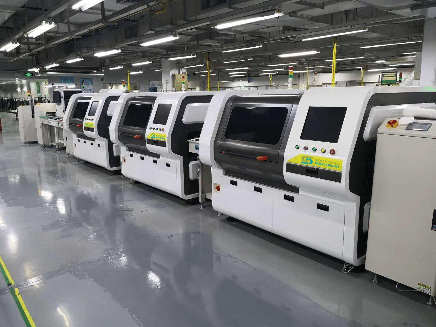
Energy-Saving Lamp PCB Assembly: Radial Auto Insertion for CFL Ballast and Light Driver Boards
Energy-saving lamp manufacturing is one of the most through-hole-intensive segments of consumer electronics. A compact fluorescent lamp (CFL) ballast board is built almost entirely from radial-lead parts — electrolytic capacitors, transistors, diodes, inductors and small transformers — that are pushed through the board and fixed in a single wave soldering pass.
That component mix is exactly what the manual insertion stations on a DIP line were never designed to handle at volume. Operators place radial parts one at a time, orientation depends on who is standing at the station, and the line only moves as fast as the slowest station on the shift.
Radial auto insertion changes that calculation. Southern Machinery builds the radial, axial and odd-form insertion stations, along with the board handling, wave soldering and cleaning equipment that turn a manual lamp-board line into a continuous SMT + THT flow.
What is a radial auto insertion machine used for on an energy-saving lamp line?
A radial auto insertion machine picks radial-lead components from tape, orients each lead to the required span, and inserts the part into the correct through-hole position on the PCB in a programmed sequence and at a programmed angle. On an energy-saving lamp board the parts handled this way are the tape-packed radial family — electrolytic capacitors, transistors and similar standard radial-lead components.
It replaces the "insert ten capacitors by hand, then the next ten" pattern with one programmed cycle, and it repeats that cycle identically on every board of the run. That consistency is what makes the downstream wave soldering and inspection steps predictable.
Southern Machinery's S-3000 Radial Auto Insertion Machine is built for this job: a dual lead span of 2.5 / 5.0 mm, a rated 18,000 CPH (approximately 10,000 CPH in practice), insertion at any angle from 0° to 360° in 1° increments, machine-vision coordinate correction, and offline programming so the next lamp board can be prepared without stopping the line.
The S-3010 series extends the same platform to four lead spans — 2.5 / 5.0 / 7.5 / 10.0 mm — for lamp and power boards that mix component sizes on one panel. Boards up to 400 × 400 mm can be handled, with PCB thickness from 0.79 mm to 2.36 mm, clinch length 1.5–2.2 mm and clinch angle 10–35°.
Why energy-saving lamp PCBA is a natural fit for auto insertion
Lamp ballast and light driver boards share three characteristics that make them well suited to automated insertion:
- A high radial component count per board. When most of the bill of materials is radial through-hole parts, insertion time dominates total assembly time — and that is the time an insertion machine compresses.
- Repeat production. Lamp products keep the same board design across long runs and repeat orders, so programming and feeder setup are amortised over thousands of boards rather than a few hundred.
- One wave soldering pass for the whole radial population. Because every radial part is inserted before the wave, line throughput is set by the insertion stations — not by the solder pot.
The same profile applies to LED lamp and light driver boards wherever through-hole parts remain, and to power supply boards such as vehicle power supplies, energy-saving power supplies and ballast.
Radial, axial and odd-form: which insertion station does what
An energy-saving lamp or lamp driver board is rarely radial-only. A practical line uses three different insertion capabilities:
- Radial insertion (S-3000 / S-3010 series) for tape-packed radial-lead components — capacitors, transistors and the standard radial family.
- Axial insertion (S4000 Axial Auto Insertion Machine) for axial-lead parts, with lead spans of 5–22 mm and insertion angles of 0°, 90°, 180° and 270°. The S4000 also runs jumper wire insertion, and can insert it independently of the component cycle.
- Odd-form insertion (S-70LD Odd Form Insertion Machine) for the parts that are neither radial, nor axial, nor SMD — connectors, transformers, relays, terminal blocks and fuse holders in trays, tubes or loose bags.
Odd-form automation is where many lamp and power board lines lose the most time. A hand-inserted odd-form connector takes roughly 4 to 10 seconds depending on operator familiarity, part orientation and how the part is presented. Odd-form defects — floating high, misinsertion, reverse insertion — are usually only caught at AOI or functional test, after the board has already passed wave soldering and cleaning, and rework takes 3 to 5 minutes per board. Vision-guided odd-form insertion removes that variability: the S-70LD uses industrial computer control with vision guidance to check polarity and lead geometry before placement, and seats every pin to the same programmed depth.
Typical application scenarios
- Energy-saving lamp and CFL ballast manufacturing — indoor, outdoor, street lamp and floodlight families
- LED lamp and light driver boards where a through-hole population remains alongside SMD
- Power supply boards — vehicle power supply, energy-saving power supply, ballast
- Appliance control boards — air conditioner, television, microwave, electric kettle, induction cooker
- EMS and ODM factories running mixed SMT + THT work for lighting and appliance customers, where the same connector or capacitor family appears across several board types
How the insertion stations fit into a complete SMT + THT line
Insertion equipment is not a standalone island. Southern Machinery supplies it as part of a line that flows in one direction:
- Board handling at the front end — magazine loader or bare-board destacker
- SMT section — stencil printing, pick and place, reflow
- SMT inspection — SPI and AOI
- THT insertion section — radial inserter (S-3000 / S-3010 series) followed by the axial inserter and the odd-form station
- Wave soldering — lead-free wave or dual-wave with PC control
- Post-wave finishing — inline auto lead cutter and PCBA cleaning
- Board handling at the back end — buffer conveyor and magazine unloader, with NG/OK routing after inspection
Each station connects to the next through the SMEMA interface, so an insertion machine can be dropped into an existing conveyor between two machines without re-engineering the line. Magazines, ESD racks, pallets and board buffers between stages keep the flow continuous during changeovers.
Only one operator is needed to supervise a running insertion line, and spare parts, sub-assemblies, retrofit kits, training and overhaul support are available for the whole line.
Selection parameters to confirm before quotation
Machine parameters must be matched to your actual board, so a quotation should be built from your Gerber data and bill of materials rather than from a catalogue. These are the values that decide the configuration:
Board side
- PCB length and width, and the maximum and minimum panel size you run
- PCB thickness, and whether the panel is routed or V-cut
- Hole diameter versus lead diameter, and the required clinch length and clinch angle
Component side
- The complete radial component list, with lead span, pitch and tape width for each
- Which components are tape-packed and which arrive loose, in tubes or in trays (odd-form)
- Component body height and stand-off above the board
- Total number of insertion points per board
Machine side
- Required cycle time and target CPH per shift
- Number of insertion heads and feeders needed to cover the component list in one pass
- Insertion angle range required by the board layout
- Whether vision correction and offline programming are needed for your product mix
- Conveyor interface (SMEMA), line height, and available floor space
- Power supply — single-phase 220 V AC 50/60 Hz is used by the S-3000 family — and shop air at approximately 0.6 MPa
- Operating environment and ESD requirements
ROI, quality and throughput: what to measure
The economics of lamp board insertion automation are usually decided by three numbers, not one:
- Insertion hours saved per shift. Count the insertion points per board, multiply by daily volume, and multiply by the measured manual time per part — measure it on the floor for about ten cycles rather than using a standard time.
- Rework avoided. Odd-form defects are the expensive ones, because they are caught late and cost 3 to 5 minutes per board to repair. Near-zero insertion defects at the station convert directly into recovered capacity.
- Line balance. A manual line is only as fast as its slowest operator on that shift. A programmed machine delivers the same cycle time on every shift, which makes throughput forecasting and delivery commitments accurate.
Auto insertion fits best at medium to high volume per SKU — roughly 500 boards or more per run with repeat orders — and where the odd-form components are standard families such as connectors, transformers, relays and terminal blocks. It fits less well below about 100 boards per run, for hand-wound or heavily non-standard magnetics, or where floor space under roughly 2 m² is available for an inline station.
Southern Machinery has been building SMT and THT PCB assembly equipment in Shenzhen, China since 2011 and serves more than 237 customers worldwide. The company supplies individual machines as well as complete SMT / THT lines that include wave soldering, board handling, inspection and cleaning, together with spare parts, training and after-sales service.
FAQ
Can one radial insertion machine handle every through-hole part on an energy-saving lamp board?
No single insertion head covers all through-hole components. Radial-lead parts are handled by the radial inserter, axial-lead parts by the axial inserter, and components that are neither radial nor axial — connectors, transformers, relays, terminal blocks — by an odd-form station. Lamp lines are normally configured with two or three insertion capabilities working in sequence.
Does an auto insertion machine replace the wave soldering machine?
No. Insertion and soldering are separate steps. The insertion stations place and clinch the components; the wave soldering machine then makes the electrical and mechanical joint for the whole through-hole population in one pass. Automation improves the soldering result because every lead is seated to the same depth.
What board sizes and thicknesses can Southern Machinery radial insertion handle?
On the S-3000, PCB size runs from 50 × 50 mm up to 400 × 380 mm, with board thickness from 0.79 mm to 2.36 mm. The S-3010 series handles panels up to 400 × 400 mm. Larger boards are available on other platforms — confirm against your panel before ordering.
Do we need to replace our existing line to add insertion automation?
Usually not. Insertion machines are designed as inline stations that accept boards over the conveyor and hand them back using the SMEMA interface, so they can be placed upstream of an existing wave soldering machine. The rest of the line — handling, soldering, cleaning — can remain in place.
Can we program new lamp boards without stopping production?
Yes. Offline programming software lets a new board be prepared on a separate computer and loaded to the machine, so changeover time on the line is limited to loading the program and setting the feeders.
What if some components are not tape-packed?
Components that arrive loose, in tubes, in trays or in bulk are handled by odd-form insertion with the appropriate feeder, or by a customised feeder designed for that component. Tray feeders, stacked tube feeders and bulk feeders are part of the standard Southern Machinery range, and non-standard feeding is one of the most common customisation requests.
Next step
Send us your lamp board Gerber data and bill of materials, and Southern Machinery will confirm the right insertion configuration, feeder set and line layout for your volume.
- Email jasonwu@smthelp.com or call +86 13602562576 for a configuration review
- Browse machine catalogues and documentation at file.autoinsertion.com
- See machine photos and application images at ph.smthelp.com
Watch the energy-saving lamp PCB insertion application in action: https://www.youtube.com/watch?v=80ZAW-eROok
Comments