
Insertion Head Disassembly & Assembly Procedures for THT Auto Insertion Machines
A step-by-step service guide to removing, disassembling and rebuilding a THT auto insertion head, with the full parts, lubricants and setup checks.
Sep 25, 2026 · Updated Sep 25, 2026 · Southern Machinery
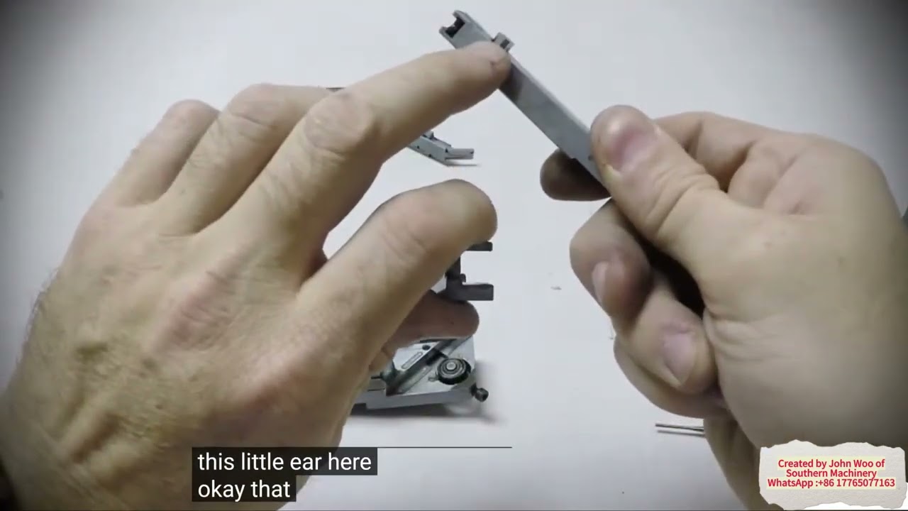
Insertion Head Disassembly & Assembly Procedures: The Complete Maintenance Sequence for THT Auto Insertion Machines
Removing an insertion head from a THT auto insertion machine is not a repair of last resort. It is a scheduled maintenance operation. Jaw clamps wear, compression springs lose tension, pusher tips score, and pivot pins develop play — and every one of those parts is reachable only with the head assembly off the machine and on a clean bench.
This guide documents the three procedures that belong together: removal of the insertion head assembly from the inserter, disassembly of the head into its serviceable sub-assemblies, and assembly of the head back to a functioning unit. The sequence and component designators below follow the published maintenance procedure for the insertion head used on radial, axial and odd-form THT auto insertion platforms. Component numbers in brackets — (1) through (15) — are the callouts from the official assembly drawings, and they are the same numbers you will use when ordering spare parts.
If you are chasing a specific fault rather than doing planned maintenance, start with the symptom instead: a head that wanders during insertion usually has a jaw guide gap problem, not a worn jaw clamp. Details at the end of this article.
---
What is this procedure used for?
This procedure is used to remove the insertion head assembly from the machine, take it apart into its individual components, and rebuild it. It is the maintenance path for:
- Replacing jaw clamps, jaw guide components and compression springs
- Replacing or re-seating a pusher tip, and correcting a sticky pusher
- Replacing scored or seized rollers and pivot pins
- Replacing the latch spring, actuator arm or slide actuator
- Full rebuild or overhaul of a head that has reached the end of its service interval
- Any maintenance where the fault is internal to the head rather than in the machine's drive or tooling
It is not the procedure for setting up a head that is already assembled and installed. Insertion head casting height, jaw guide gap, head centering and CTA-to-head alignment are separate adjustments — they are listed in the setup sequence section below, and they must be completed after the head is rebuilt and reinstalled.
---
Why the insertion head has to come off the machine
The insertion head is a small, tightly stacked assembly. The jaw guide, jaw clamps, compression springs, slide actuator, actuator arm and pusher tip are all nested inside the head housing and the block. There is no access path to the springs or the clamps while the head is mounted on the head drive shaft.
The published procedure is explicit that the head is removed first and serviced on the bench. That is also the sensible order for a production line: a head swap takes the machine out of service once, instead of keeping it down while a technician works inside a confined assembly. On a well-run THT insertion cell, a serviceable spare head is kept on the shelf precisely so that this work happens off-line.
---
Safety prerequisites — do not skip these
Two conditions are non-negotiable before the first step:
- Power down the machine. The procedure is documented with the machine stopped. Never work on the head drive assembly with the machine energised.
- Perform Lockout/Tagout (LOTO) according to your local procedures. The published procedure carries an explicit warning on this point: the machine must be powered down and the local LOTO procedure performed to ensure personal safety. Treat this as a personal-safety requirement, not a formality.
You will also need a clean, well-lit bench, the Insertion Head Drawings section of your Maintenance Support Document (the drawings are required for part identification and part ordering), and a small set of hex keys and screwdrivers. The head assembly is heavy enough to need both hands when it comes free of the shaft clamp — plan for where it is going before you open the clamp.
---
Step-by-step: removal of the insertion head assembly
To remove the insertion head assembly, proceed as follows.
- Power down the machine and perform Lockout/Tagout according to local procedures.
- Open the inserter front cover for access to the insertion head drive assembly.
- Manually rotate the insertion head assembly 90 degrees clockwise.
- Loosen the hex jam nut and set screw. The head drive area carries a shaft clamp set screw, a tooling pin, a hex nut and a set screw — identify each on the drawing before loosening anything.
- Loosen the socket set screw and remove the tooling pin.
- While holding the insertion head assembly, open the shaft clamp.
- Slide the insertion head assembly toward the back of the machine until the pusher is disengaged from the shaft.
- Remove the insertion head assembly from the machine. End of procedure.
Two points of discipline matter here. First, the 90-degree clockwise rotation is what gives you access to the clamp hardware — rotate before you reach for a wrench. Second, step 6 and step 7 are one continuous motion in practice: open the clamp, hold the head, and slide it back until the pusher clears the shaft. Let the head hang or drop and you will damage the pusher or the shaft.
---
Step-by-step: disassembly of the insertion head assembly
With the head on the bench, disassemble as follows.
- Remove the cap screw and latch spring.
- Remove the cap screws and top plate assembly.
- Remove the actuator arm.
- Remove the jaw guide assembly and the slide with the pusher tip assembly.
- Remove the set screws, then remove the cap screws and block. The jaw guide assembly and the pusher tip assembly are now separate from the housing.
- While taking care to prevent the spring from flying loose, slide the actuator down and remove it from the jaw guide. This is the step where small parts go missing. Work over a tray, and cup the assembly with your hand as the actuator clears.
- Remove the right jaw clamp, left jaw clamp and two compression springs.
- Push up and turn the tip clockwise to release it from the socket in the pusher tip, then remove the tip and spring.
- Centre the pin in the slot by pushing the pusher tip into the pusher. Hold it in this position.
- Remove the pin from the pusher.
- Remove the pusher tip and compression spring from the pusher.
- Remove the compression spring from the pusher tip.
Lay the parts out in the order they came off. The jaw clamps are a matched left/right pair and the two compression springs behind them are not interchangeable with the springs in the pusher stack — mixing them up is the most common cause of a head that will not hold a lead squarely after reassembly.
---
Step-by-step: assembly of the insertion head
To assemble the insertion head assembly, proceed as follows. Refer to the illustrations on the pages that follow in the Maintenance Support Document.
- Lubricate with anderol and install pusher (1) into slide (12). Set aside.
- Lubricate both cam surfaces on the slide actuator (6) with anderol.
- Apply a light coat of anderol into the slot and both grooves of the jaw guide (3).
- Install the compression springs (2) into the jaw guide (3).
- Install the right and left jaw clamps (4 and 5) over the springs and onto the jaw guide. Hold the assembly together until the slide actuator (6) is installed — the springs are under load and will push the clamps out.
- Install the slide actuator (6) over the jaw guide to secure the left and right jaw clamps to the jaw guide.
- Install the compression spring (7) by inserting the spring through the opening between the slide actuator and the jaw guide.
- Clean the threads and apply Loctite 242 to the cap screws.
- Be careful not to separate the slide actuator from the jaw guide. Install the jaw guide into the block (8).
- While keeping the jaw guide in the block, install the cap screws (9) into the block. Do not tighten the screws.
- Install the dowel pin (15) into the block and jaw, then tighten the cap screws (9). Check for movement from front to back. The dowel pin locates the jaw; if you tighten the cap screws before the pin is seated, the jaw will sit off-square and the head will not centre correctly.
- Install the jaw guide assembly (3) into the housing.
- Install the arm actuator (14) into the top plate assembly (10).
- Install the slide (12) into the housing (11).
- Install the top plate assembly (10) to the housing (11) and secure with cap screws (13).
After assembly, reinstalling the head on the machine reverses the removal sequence: seat the assembly on the shaft, engage the pusher, close the shaft clamp, refit the tooling pin and socket set screw, tighten the hex jam nut and set screw, and rotate the head back to its running position.
---
Tools, lubricants and consumables
Plan the job around this list rather than discovering it mid-rebuild:
| Item | Purpose in this procedure |
| --- | --- |
| Anderol lubricant | Pusher (1), slide (12), both cam surfaces of the slide actuator (6), and the slot and grooves of the jaw guide (3) |
| Loctite 242 (medium-strength threadlocker) | Cap screws — threads cleaned before application |
| Hex keys and screwdrivers | Cap screws, set screws, socket set screw, hex jam nut |
| LOTO locks and tags | Machine isolation before the front cover is opened |
| Jaw clamps (left and right) | Wear item — matched pair |
| Compression springs | Wear item — head stack and pusher stack are different parts |
| Pusher tip | Selected from the machine's Pusher Tip Selection Chart |
| Dowel pin (15), cap screws (9) and (13), latch spring | Service parts per the Insertion Head Drawings |
| Maintenance Support Document | Assembly drawings for identification and ordering |
| A clean bench and a parts tray | Spring retention during step 6 of disassembly |
Part numbers are revision-specific. Use the Insertion Head Drawings in your Maintenance Support Document — or ask Southern Machinery to confirm the correct revision for your head — rather than ordering from a photograph.
---
Where this fits in the insertion head setup sequence
A rebuilt head still has to be set up. The four interlocking adjustments are documented as a sequence, because each one moves the datum that the next one depends on:
| Adjustment | What it sets | Prerequisite |
| --- | --- | --- |
| Insertion head casting height | Distance from the bottom of the plate under the CTA to the top of the rotary table | Plate squared to the upper frame |
| Jaw guide gap | Clearance between the jaw guide block and the head housing | Machine powered down, head removed |
| Insertion head centering | Head axis relative to the board and tooling | Follows the jaw guide gap adjustment |
| CTA-to-head alignment | Alignment of the CTA component transfer to the insertion head tooling | Head up adjustment, head centering, sequencer chain at zero position |
Two of these are worth understanding before you schedule the work, because they cause faults that look like something else entirely:
- Casting height is a collision risk, not just an accuracy setting. If the distance from the plate under the CTA to the top of the rotary table is wrong, the CTA can interfere with components already on the workboard. The published procedure sets it with a gauge block — the published value is 34.37 mm (1.353 in.) — placed next to the rear rotary table support bearing as the reference point, adjusted until the block slides under and back out from beneath the CTA transfer plate with only slight friction. The four head casting bolts are then retightened, the setting rechecked, and torque seal applied over the set screw threads. The plate settings themselves are set at the factory and should not be changed.
- CTA alignment uses the machine's own diagnostics. The technician calls IM Diagnostics → Quickstart option 2, "Set Up Critical Axis Positions", zeros the Head Theta, Head Vertical and Head Insert axes, fits the setup tool into the insert tooling guide jaw, and then extends the CTA component transfer to the head. The leads on the setup tool should seat in the bottom of the "V" slots; if they do, no further adjustment is needed.
Southern Machinery publishes the companion procedures for the jaw guide gap, head centering and casting height, so a rebuild does not have to be a research project.
---
Typical application scenarios
Head rebuilds are planned maintenance, and planned maintenance looks different depending on the plant:
- EMS / contract manufacturing — high-mix, high-changeover sites where a single insertion platform runs several product families. Head service is scheduled around changeover windows, with a spare head kept serviceable.
- Automotive electronics — thicker leads and heavier insertion forces accelerate jaw clamp and pusher tip wear; rebuild intervals are driven by a fixed insertion count rather than by calendar time.
- Home appliance and white goods — air conditioner, television, microwave, induction cooker and electric kettle control boards, where radial and odd-form heads run continuously on long, stable product runs.
- Power supply and LED drivers — vehicle power supplies, energy-saving power supplies and ballast boards with mixed through-hole content.
- Industrial control and instrument assembly — lower volume but tighter quality tolerance, where a mis-clinched or off-centre lead is a functional failure rather than a cosmetic one.
- Legacy platform support — UIC/Universal-style and similar auto insertion platforms where the head is still the most productive way to place through-hole components and no drop-in replacement exists.
---
How this fits into a complete SMT/THT PCB assembly line
The insertion head is one component of one station in a larger line. Understanding where the head sits makes the maintenance plan easier to justify:
- SMT section — stencil printing, pick and place, reflow, SPI and AOI handle the surface-mount content.
- THT section — radial, axial, odd-form and terminal auto insertion machines place through-hole components, with the insertion head as the point of contact between machine and board.
- Wave soldering — the assembled board is soldered, with lead clinching from the insertion head determining how well every joint forms.
- Post-solder — lead cutting, cleaning, coating and inspection follow.
- Board handling and material management — loaders, unloaders, buffers, conveyors, feeders and reel storage keep the line fed and in balance.
Auto insertion heads are frequently the constraint in step 2. A head that is run to failure does not fail gracefully: insertion quality degrades first, then lead clinching degrades, and the defect only becomes visible after wave soldering — several stations downstream and long after the actual cause. Rebuilding heads on a fixed interval, off-line, with a spare head available, keeps the THT section's contribution to line yield predictable. Southern Machinery supports the whole line — SMT, THT, wave soldering, board handling and inspection — along with the spare parts, sub-assemblies, retrofit kits and training that keep it running.
---
Key parameters to confirm before you order parts
Do not order parts or schedule downtime before confirming the following. These are the questions that determine which parts fit your head:
- Head type and platform — radial, axial, odd-form or terminal insertion head; UIC/Universal-style platform or a different OEM family.
- Head part number and assembly revision — the jaw guide, jaw clamps, pusher tip and block are revision-specific.
- Component lead diameter and span — determines the jaw clamp and pusher tip combination; the tip is selected from the machine's Pusher Tip Selection Chart.
- Push rod / slide condition — a scored slide or bent push rod is a replacement, not an adjustment.
- Roller condition — whether the head rollers rotate cleanly; a scored or seized roller is a part replacement.
- Spring set — head-stack and pusher-stack compression springs are different parts and are not interchangeable.
- Available special tooling — the VSL T Anvil to Cutter Former (Window Opening) and equivalent setup tools are required for the alignment steps after the rebuild.
- Consumables in stock — set screws, cap screws, compression springs, dowel pins, jaw clamps and pusher tips are all consumable over a head's life.
- Spare head availability — whether a serviceable spare head can be held to keep the line running during the rebuild.
Southern Machinery can confirm the correct configuration for your specific insertion head rather than having you guess from a drawing.
---
ROI, quality and throughput perspective
The case for scheduled head rebuilds rests on three numbers a production manager already tracks:
- Unplanned downtime. A head failure during a production run stops the machine and, on a balanced line, starves the wave solder and downstream stations. A bench rebuild during a scheduled window costs a fraction of that.
- Rework and scrap. Jaw clamp wear and spring fatigue produce off-centre and under-inserted leads. Those defects are usually detected after wave soldering, so each one carries the full cost of a soldered board, not just an insertion cycle. A rebuild restores insertion accuracy at the source.
- Spare parts spend. Replacing springs and clamps on a planned interval is cheaper than replacing a jaw guide, block or pusher assembly damaged by running a head to the point of mechanical failure. Southern Machinery supports head maintenance with spare parts, sub-assemblies and repair kits, so the low-cost wear items are available when the planned rebuild is scheduled.
The compounding benefit is consistency. A head that is rebuilt to the same specification on every interval produces the same clinch quality on every board, which is what makes downstream inspection data meaningful and line yield predictable.
---
Frequently asked questions
What is the insertion head disassembly procedure used for?
It is used to take the insertion head assembly apart on the bench so that internal wear parts — jaw clamps, compression springs, pusher tip, rollers and pivot pin — can be replaced, and to rebuild the head afterwards. It covers removal of the head from the machine, disassembly into sub-assemblies, and the 15-step assembly sequence.
Can I disassemble the insertion head while it is still on the machine?
No. The procedure requires the machine to be powered down with Lockout/Tagout performed, and the head assembly to be removed from the head drive shaft before disassembly begins. The internal springs and jaw clamps are not accessible with the head mounted.
Which lubricant and threadlocker does the assembly procedure specify?
Anderol lubricant is used on the pusher, the slide, both cam surfaces of the slide actuator, and the slot and grooves of the jaw guide. Loctite 242 is applied to the cap screws after the threads are cleaned. No other lubricant is specified in the procedure.
How long does an insertion head rebuild take?
That depends on the head type, the spares you have on hand and whether the setup adjustments that follow are included. Confirm the interval and the parts list with Southern Machinery before scheduling the downtime, so the rebuild and the setup are completed in one window.
What has to be done after the head is reassembled and reinstalled?
The head must be set up again. The documented sequence is insertion head casting height, jaw guide gap, insertion head centering, and CTA-to-head alignment — in that order, because each adjustment establishes the datum for the next.
Do I need specialist tooling?
Yes. The procedure references the Insertion Head Drawings in the Maintenance Support Document for part identification and ordering, and the alignment steps that follow the rebuild require setup tooling — for example the VSL T Anvil to Cutter Former (Window Opening). Southern Machinery can confirm the tooling and spares list for your platform.
Does Southern Machinery support heads on legacy insertion platforms?
Yes. Southern Machinery services legacy SMT and THT platforms with spare parts, sub-assemblies, retrofit kits, repair kits, upgrading, overhaul and operator and maintenance training — including legacy auto insertion electronics repair.
---
Get the right procedure, the right tooling and the right spare parts
Southern Machinery has supplied SMT and THT PCB assembly automation equipment since 2011 from Shenzhen, China, and supports more than 237 customers worldwide. Beyond complete line solutions across SMT, THT, wave soldering, board handling and inspection, we keep the THT section of those lines running with spare parts, sub-assemblies, retrofit and repair kits, upgrading, overhaul and training.
If you are planning an insertion head rebuild — or a head has already failed and you need the parts identified quickly — send us the head platform and part number and we will confirm the correct revision, the wear-part set and the tooling you need.
Contact Jason Wu — jasonwu@smthelp.com | +86 13602562576 | www.smthelp.com
- Browse machine and spare parts catalogues at file.autoinsertion.com
- See machine photos at ph.smthelp.com
- Related reading: Insertion Head Jaw Guide Gap Adjustment and Radial Insertion Machine Preventive Maintenance & Repair Guide
Comments